This Tutorial references the following Rhino File: 3DP_Prep.3dm (All Layers should be OFF)
Rhinoceros defines Surfaces with Curve Geometry moving in the ‘U’ and ‘V’ Direction, called ‘Iso-Curves’. The more Curves we have to define a Surface, the more control we have over our end product. We can create Surfaces from Curves in multiple ways; in this tutorial we will discuss these methods of Surface Creation through Curve Geometry.
To begin, there are basic methods to create Surface Geometry, and then there are more complex methods. Basic Methods are usually dependent upon existing Surface Geometry. Complex methods are usually Surfaces defined by Curve Geometry. We will discuss these methods in order from most basic, to most complex. Learning the fundamentals first, is highly recommended. Regardless of the Method, it is important to recognize the more curves you have to define a surface, the more control you have over the way it looks. Alternately, less curve geometry will still define a surface, but leave some of the work to the programming side of Rhino. Turn the ‘PLNR’ Layer ON, and expand your PERSPECTIVE Viewport.

You should have a gray surface, with (1) Green & (1) Cyan Closed Curves. During this discussion, we will utilize Commands from the ‘Surface’ Drop-Down Menu in Rhino. Text Commands will also be provided.
| In this scenario, we assume that we have duplicated Surface Edges with the DUPEDGE Command, and JOINed those Edges into one Closed Curve. This is representative of the Green and Cyan Curve Geometry on your ‘PLNR’ Layer. Orbit around the object, and select the CYAN Curve; then type PLANARSRF into the Command Prompt and Press ENTER. | 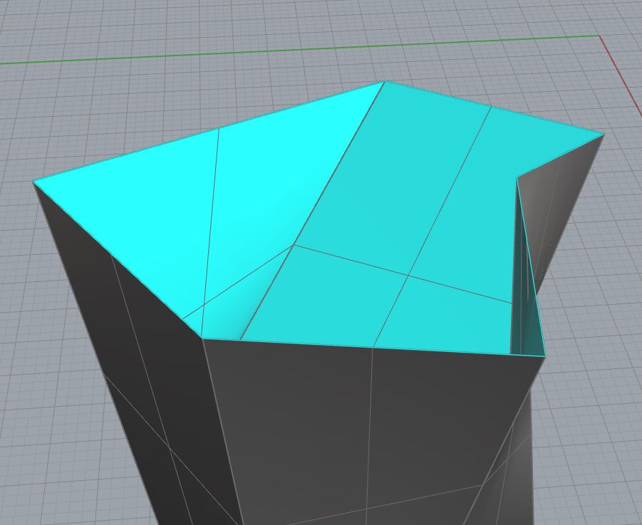 |
| You should see a new surface appear within your Closed Cyan Curve. The ‘Planar Curves’ Command uses Planar Surface Edges, or Curves to generate a Planar Surface. Planar indicates that the Geometry is strictly 2-Dimensional, and does not shift in the ‘Z’ Direction (aka, FLAT) We’ve used a Closed Curve to Generate this Surface, and it is Planar; however, you can also use singular curves, or you could use Surface Edges. DELETE the Surface you’ve just created, and the Cyan Curve. Then try the PLANARSRF Command once more, but this time, select each surface edge where the Cyan Curve was previously located. You will achieve the exact same Surface you’ve created previously. | 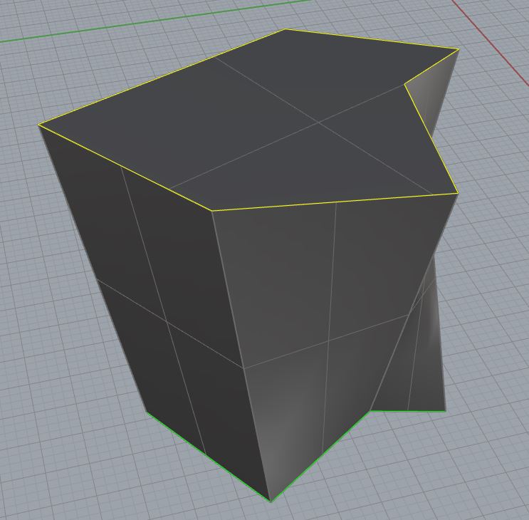 |
| The Planar Curves Command, assumes you have Planar Geometry to Create a Surface from. What if your Curve Geometry isn’t Planar? You can no longer use PLANARSRF, and you will have to make use of a separate command called ‘Patch’. Orbit around your Geometry until the Green Curve is visible. Select the Green Curve and type PATCH into the Command Prompt. Press ENTER and a new window will appear. |  |
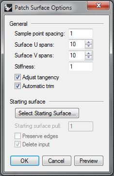 |
This new window is your ‘Patch Surface Options’. It allows you to control: Surface Resolution; how the Surface connects to existing geometry; and how the Surface Iso-Curves are defined. Beginning from the top, Sample Point Spacing controls how your surface is defined. If you are using curves to define your Patch Surface, setting a higher value will ensure the Surface is created and constrained closer to the exact locations of selected curve geometry. Surface U Spans & Surface V Spans will adjust how many Iso-Curves are generated in each direction. More Iso-Curves = more control points for editing afterward. Stiffness Rhino builds the patch surface by first finding the best fit plane through the selected and sampled points along curves. Then the surface deforms to match the points and sampled points. The Stiffness setting tells how much you allow the best fit plane to deform. The bigger the number, the “stiffer” and more rectangular and planar the resulting surface will be. [Excerpt from Rhino V5 Help Menu] Adjust Tangency will constrain your Patch Surface to the tangent direction of Surfaces; if you are using Surface Edges to define your Patch. (We are using Curves in this example) Automatic Trim will find/assume a Surface Border, and trim your patch accordingly. We could continue with the final options, but let’s keep it simple for now. You can play with these options as much as you like, and press the ‘Preview’ Button to get an idea of what each setting controls. The Rhino Help menu is also very useful. Press ‘OK’ to continue. |
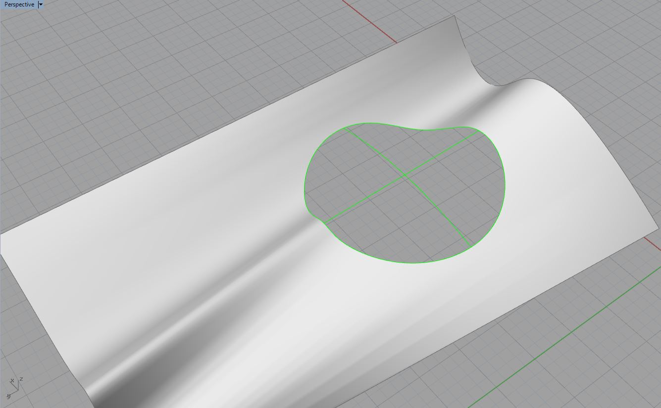
| If you are successful, you should have something like Fig 2.3. This is a very simple idea of how to use this command. This command is more commonly used with ‘U’ and ‘V’ Iso-Curves to generate a patch surface. In Fig 2.4, you can see an example of the of ‘U’ and ‘V’ Curves appearing in green. This isn’t in your Rhino File, but your welcome to replicate the scenario or just follow along. Type PATCH, select the green curves, and press ENTER. When the ‘Patch Surface Options’ appear: Sample Point Spacing = 1000; Surface U Spans = 50; Surface V Spans = 50; Stiffness = .5Select OK, and we get something similar to Fig. 2.5. Because we used Iso-Curves AND a Border Curve, we have more control over the Surface Creation.Regardless of your choice, this is a very common way to create a Surface from Curves in a space that is not planar. Please visit the Rhino Help menu for additional assistance and notes. It is extremely helpful when describing and presenting the information in an understandable fashion. It also includes video demonstrations. | 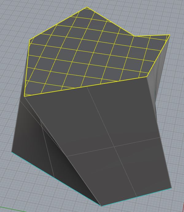 Fig. 2.3 Fig. 2.3 |
Fig. 2.4 Fig. 2.5
| Lofting is a simple form of Surface Creation, and utilizes Curve Geometry to define itself. We create any amount of curve geometry (>1) moving in ONE Direction only. This means that we are creating ‘U’ Iso-Curves, or ‘V’ Iso-Curves. Turn OFF your ‘PLNR’ Layer, and turn ON your ‘CREATE’ Layer. Make your Perspective Viewport Active.Next, find the Green Curve Geometry on this layer, and select all (3) Curves. Type ZS into the Command Prompt (Zoom Selected). Type LOFT into the Command Prompt and press ENTER. | 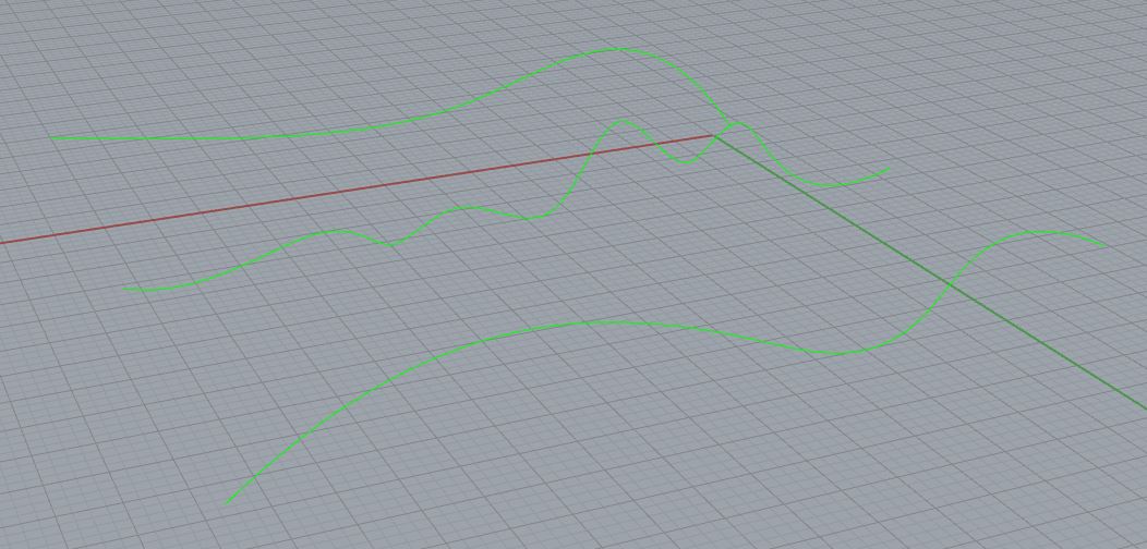 |
 |
A window appears, titled ‘Loft Options’. Because we have only defined this surface with (2) Edge Curves, and (1) Iso-Curve; and the Curves are only moving in one direction, (‘U’ or ‘V’)- we have to tell Rhino how to figure out the rest of the Surface Iso-Curvature. Changing the Style Options will adjust how the Surface constrains itself to your defining Iso-Curves. Play with these settings, and Press PREVIEW to get an idea of what each Style Option controls. Closed Loft is set to OFF by default, but will attempt to create a Closed, Solid Polysurface if selected. Match start tangent & Match end tangent will constrain your Lofted Surface Edges to existing Surface Geometry. Align Curves will take you back to your Rhino Viewport to switch the Curve Direction; if you notice your loft is ‘odd’ looking, it may be because of a curve directional problem. Make sure they are ALL moving in the same direction. The final options in this window control how precise your Lofted Surface will constrain itself to the defining Curve Geometry. See the Rhino Help Menu for more detailed information. Leave everything as default for now, and Select OK. |
| You should have a surface that resembles the image to the right. Lofting is considered the ‘bridge’ between Basic to Complex Surface Commands. Let’s move on to the Complex Commands, starting with ‘Edge Curves’. Select the (4) Cyan Curves on the ‘CREATE’ Layer, and type ZS into the Command Prompt. | 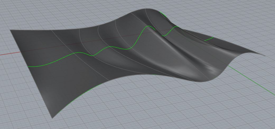 |
| The Edge Curves Command uses (2), (3), or (4) Curves to define a surface. The Curves can be moving in any direction (‘U’ or ‘V’), and for best results, the Curves should form a closed curve if they are JOINed. Leave them as single Curves for now, select all (4) Cyan Curves, and type EDGESRF into the Command Prompt. | 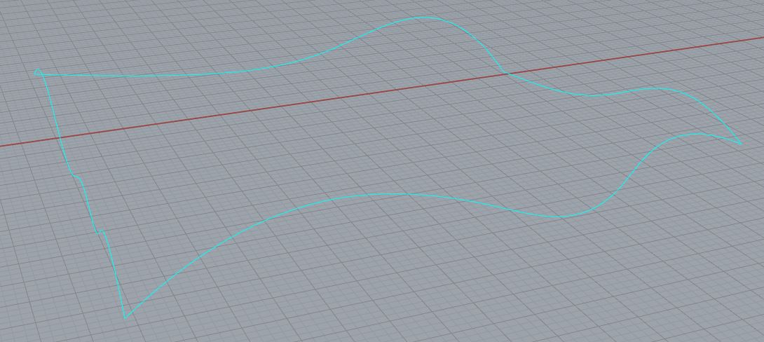 |
| Because we have Curve Geometry defining both ‘U’ and ‘V’ Directions, more specifically, the Surface Edges; we gain more control over our output. The Edge Curves Command defines the Surface Edges with the Curves you’ve selected, and carries these Iso-Curve definitions throughout the interior Iso-Curves. Thus, you have a more defined surface. | 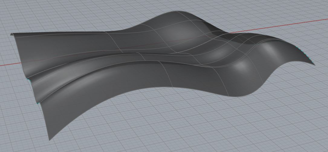 |
| Curve Networking involves more curve geometry than any other Surface Creation Command. This Process offers more control than any other Surface Command, but requires more experience & organization. To create a Curve Network, you must first create Edge Curves for your prospective surface. After creating the Edges, you must begin defining interior Iso-Curves. They can move in either direction, and you can have as many as you like. Type NETWORKSRF into the Command Prompt and Press ENTER. | 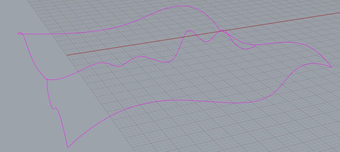 |
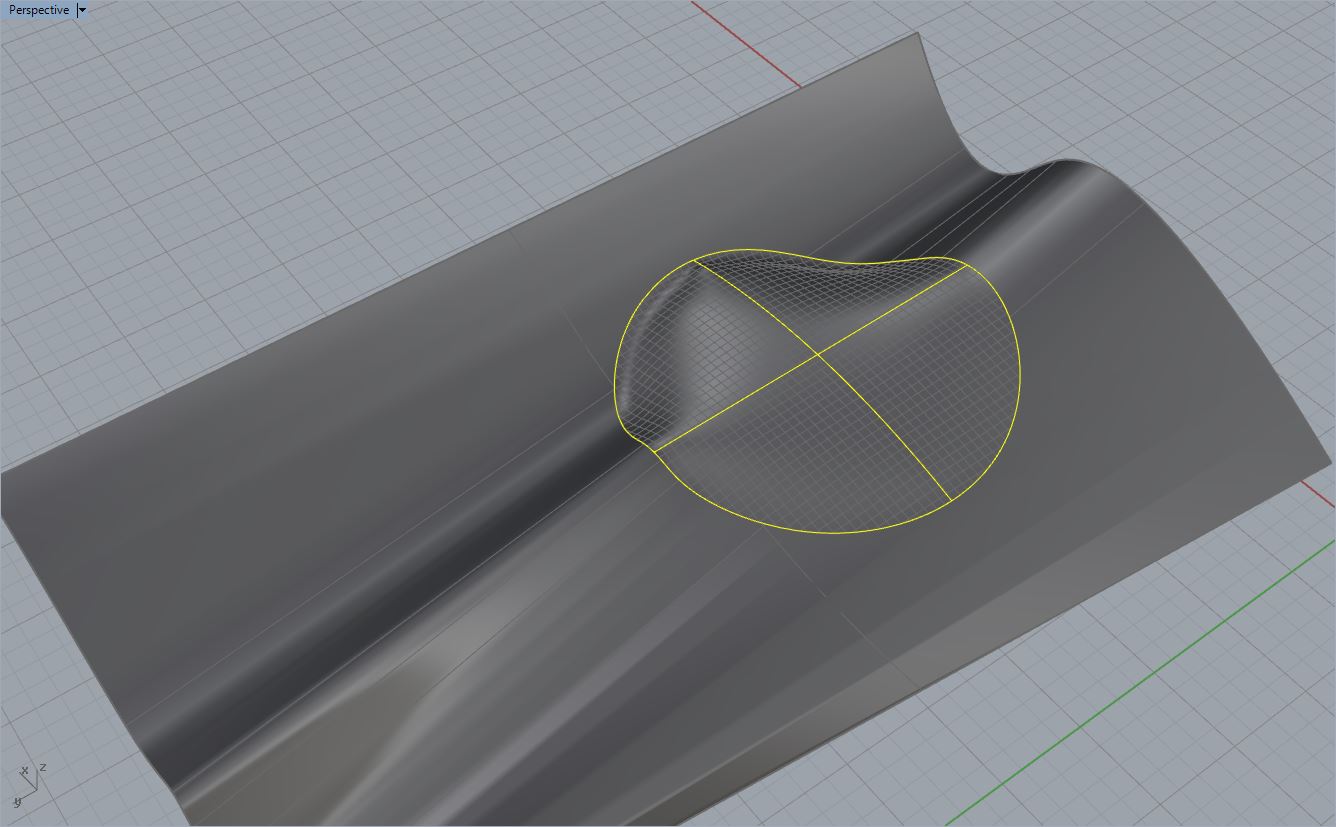
| The Command Prompt will read: ‘Select curves in network’. For your Network Surfaces to work correctly, there is a trick that tends to help more often than not: First, you must select the curves running in ONE Direction only. The image on the right shows you an example; each of the highlighted yellow curves is a Curve moving in the ‘V’ Direction. | 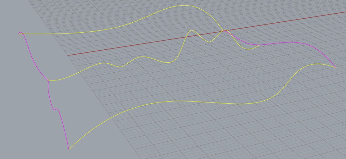 |
| Next, select the remaining curves running in the opposite direction. In this scenario, we only have (2) Curves running in the opposite direction (‘U’ Direction). The reason we select our Curve Geometry in this manner is because of the way Rhino processes the defining geometry. Rhino will attempt to ‘Automatically Sort’ your Curves; meaning, it will figure out which Curves are Edge Curves vs. Interior Iso-Curves. Rhino will figure it out if you have some basic Curve Geometry and just select it all at once; but there are scenarios in which your defining Curves are complicated, and Rhino may need some help figuring it all out. Press ENTER. | 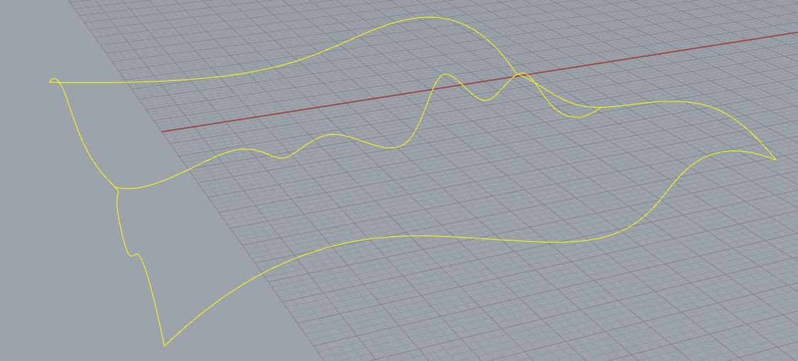 |
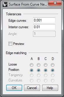 |
A window appears, titled ‘Surface from Curve Network’. Rhino will attempt to create your surface from the selected Curve Geometry; but sometimes, the curves are too complex or unique. To adjust the surface to the EXACT locations of all your defining Curve Geometry, you must indicate the allowable tolerances Rhino may adjust itself to. Edge Curves sets the allowable tolerance the surface may deviate from on your Edge Curves. Interior Curves sets the allowable tolerance the surface may deviate from on your Interior Iso-Curves. Edge Matching is a final area of options to adjust the Edges of your Surface to existing Geometry. Notice the A,B,C & D Labels; these correspond with your Surface Edges. If you look back to your Rhino Viewport, you will see your Edge Curves labeled with these Letters. You may adjust each edge separately from your options menu. Loose allows Rhino to ‘loosely’ adjust the Edges of your Surface to your Curve Geometry. Position attempts to maintain the Surface Edges as you have previously defined by Curve Geometry or Existing Surface Edges. Tangency is only available when one of your Surface Edges is ‘Tangent’ to another surface. If you are creating a Network Surface, and your ultimate goal is to JOIN these Surfaces into one Valid, Solid Polysurface- then it is HIGHLY recommended that you use Surface Edges as apart of your Curve Network- rather than Curve Geometry. Curvature options are rarely used, but typically involve cases where your defining Curve Geometry is square. |
| Accept the default settings, and Press ENTER. The Options window disapears and leaves you with your final surface: A Surface, created from a ‘Network’ of defining Edge & Interior Iso-Curves, moving in the ‘U’ and ‘V’ Direction. This command gives you ultimate control over your Surface Creation, because you are defining surfaces in the exact same manner that Rhino defines a Surface. | |
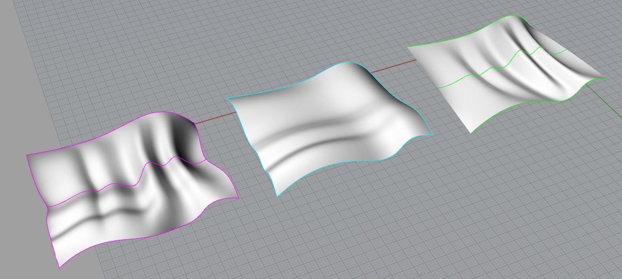
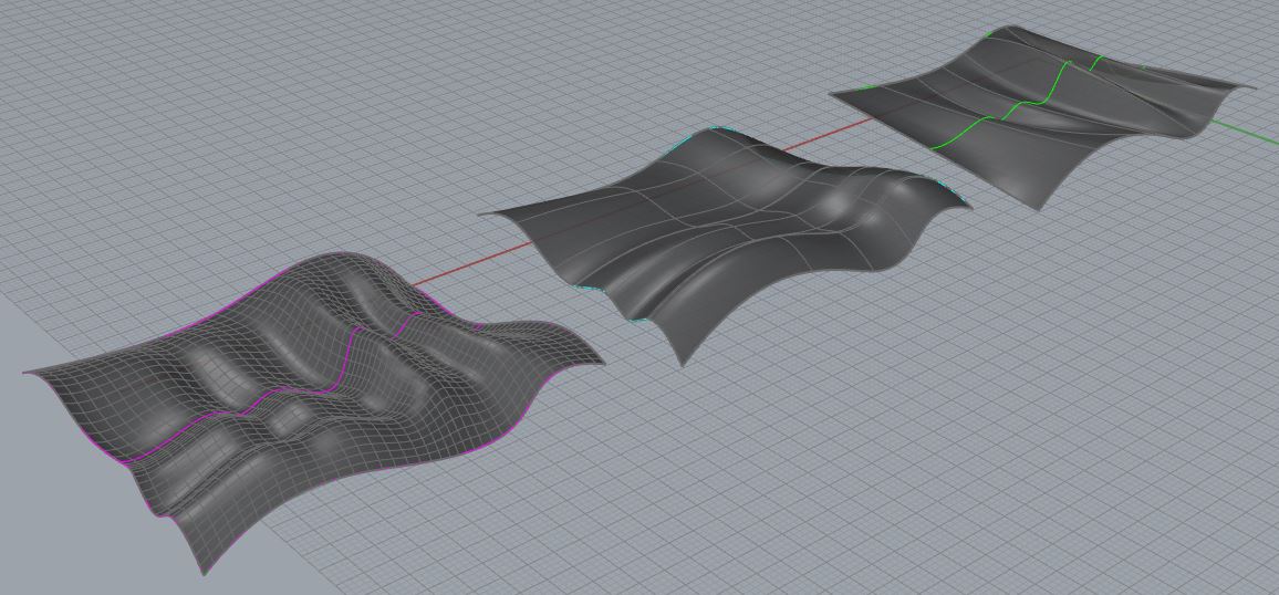
Zoom out on your ‘CREATE’ Layer; if you’ve spent the time creating a Surface from Lofting, Edge Curves, and Curve Networking, you should see an example of each Surface in your Perspective Viewport. Try switching between Rendered and Shaded Viewports, and inspect the differences between each surface. Lofting offered minimal control over the output Surface. Edge Curves offered a little more control; but, Curve Networking offered the most control out of them all. You can see these differences just by looking at the Surfaces. Note: The Curves used to define each of these surfaces are all the same. Edge Curves Command utilized the (2) Edge Curves from the Lofted Surface; & the Curve Network Command used (2) Edge Curves from the Lofted Surface, (1) Interior Curve from the Lofted Surface, and (2) Edge Curves from the Edge Curve Surface. Ultimately, there was no deviation between the Curves, yet, with different commands, and more defining geometry, we created a more controllable output Surface.
Next Recommended Tutorial: Surface to Solid
END
Created by: P. Zach Ali
Date: 10.22.2013
[…] or reduce definition. Creating Surfaces from Curves is covered in a separate Tutorial located here; but before moving forward, make note of the […]
[…] Next Recommended Tutorial: Creating Surfaces from Curves […]
[…] Next Recommended Tutorial: Creating Surfaces from Curves […]
[…] Duplicating a Face Border will extract the Exterior Surface Edges, rather than all borders. Type DUPFACEBORDER into the Command Prompt, then select your Surface. Press ENTER. You will extract the Surface Edges as indicated in Fig. 1.8. This eliminates the time involved with deleting any interior Curve Borders. Furthermore, ALL of these CURVE FROM OBJECT commands allow a user to extract Surface Edges as Curves. These Curves are what defines a Surface. You can edit these Curves as much as you like, by turning on your control points and adjusting the Control Point Locations. To turn on Control Points, Press the F10 Key (POINTSON) and select your geometry. The points that appear are capable of being dragged and edited. F11 (POINTSOFF) will turn your Control Points off. Once adjusted to your preference, you can re-create the Surface with Surface from Curve Commands. […]
[…] continue working with the same surface. In our previous tutorial, we discussed Surface Creation through Curve Geometry. We can use these Commands and Methods with our current scenario. Begin by selecting your Surface, […]
[…] continue working with the same surface. In our previous tutorial, we discussed Surface Creation through Curve Geometry. We can use these Commands and Methods with our current scenario. Begin by selecting your Surface, […]
[…] continue working with the same surface. In our previous tutorial, we discussed Surface Creation through Curve Geometry. We can use these Commands and Methods with our current scenario. Begin by selecting your Surface, […]