This Tutorial references the following Rhino File: 3DP_Prep.3dm
Rhinoceros is considered a ‘Surface Modeling’ Program- so what indicates a Surface vs. Solid? This tutorial discusses the details and preparation required for Users to create a Valid Solid within Rhinoceros 3D. More specifically, for 3D Printing End-Processes.
To begin working with Surfaces in Rhinoceros, we must first investigate ‘Why?’, and furthermore, ‘What?’ a Surface Modeling Program is. Rhinoceros is a Surface Modeling Program, so what exactly defines a Solid vs. Surface within the Application Environment? To begin, turn on the ‘BOX’ Layer, make the PERSPECTIVE Viewport active, and turn on SHADED Rendering. (CTRL+ALT+S)
Next, SELECT the BOX, and type WHAT into the Command Prompt. A new window should appear titled ‘Object Description’, with information on your selected geometry. The ‘Geometry:’ details are the parameters we should inspect.
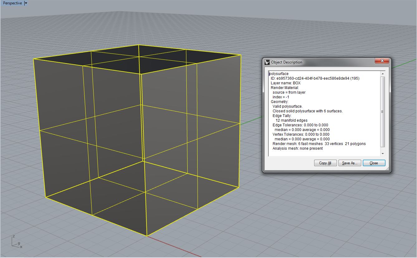
-‘Valid polysurface.’ : We know that our Geometry is a Polysurface; ‘Poly-‘ meaning ‘many’, and surface, will equate to ‘Many-Surfaces’.
-‘Closed solid polysurface with 6 surfaces.’ : This indicates that our Polysurface is made from (6) Surfaces, joined together.
-’12 manifold edges’ : ‘Manifold’, in simpler terms; means that our Surface Edges are meeting at the exact same point in space.
What should we take from this information? Well, we know that Rhino creates ‘Surfaces’, and when those Surfaces are JOINed, they become ‘Valid’, or ‘Invalid’ Polysurfaces. We also know that a ‘Solid’, in Rhino, must be made up from several surfaces; and furthermore, the edges of each surface must be meeting at precisely the same point in space. Expanding on this information, Rhino allows a user to JOIN surfaces together. Just because we JOIN them together, does not make a ‘Valid’ Polysurface. If we try to JOIN complex surfaces, surfaces that do not have manifold edges, or if our surface direction is facing incorrectly, we will usually end up with an ‘Invalid’ Polysurface. In short, to create a ‘Solid’, in Rhino- we must ensure that our Surface Geometry has the following properties:
1. SURFACE DIRECTION- All Surfaces are facing the right direction
2. SURFACE EDGES- All Surfaces have Manifold Edges
3. SURFACE VALIDATION- All Surfaces, when JOINed, create a Valid Polysurface
| All Surfaces in Rhino are facing a certain direction. They have ‘Front Faces’, and ‘Back Faces’. This is primarily used for Rendering purposes, but can also cause problems when joining complex surface geometry. For example, let’s SELECT the BOX Geometry on our ‘BOX’ Layer. Type ‘DIRECTION’ into the Command Prompt. Your Geometry should have several arrows protruding from each surface, indicating each surface’s direction. All arrows should be pointing out, from the inside of the box. Every surface on this BOX Layer, is pointing outward, indicating they are all facing the correct direction. Let’s say that we created these surfaces individually; press ENTER to exit the DIRECTION command, select BOX Geometry, then type EXPLODE into the Command Prompt. We now have (6) Separate Surfaces, they are all facing the same DIRECTION. Select one of these surfaces, and type FLIP into the command prompt; then type ‘DIRECTION’ into the Command Prompt. This single surface is now facing into the BOX Geometry. This is called your Surface ‘Normal’, and ALL Normals should be facing the same DIRECTION for Polysurfaces to be Valid. | 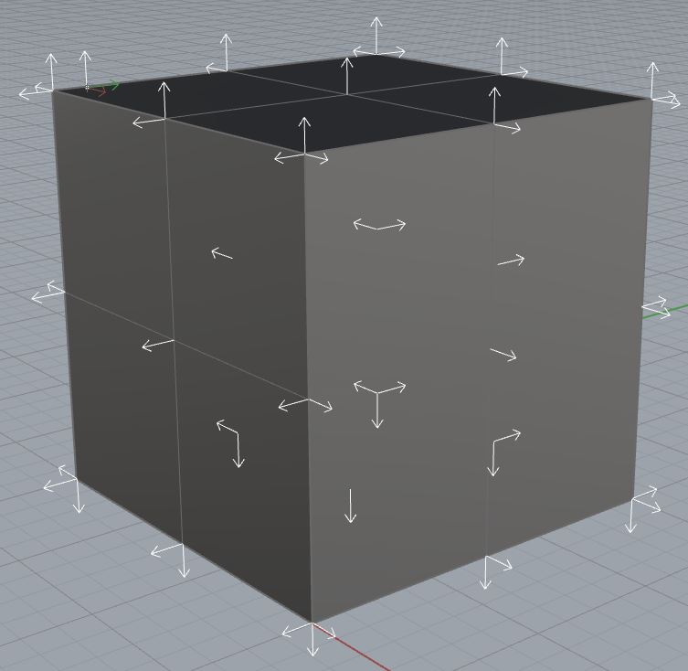 |
The problem, is that we don’t always know which direction our surfaces are facing while 3D Modeling. To solve this issue, follow the steps below: (Click here for a Screenshot)
Type OPTIONS into the Command Prompt
In the Rhino Options Menu, Expand the ‘View’ Parameter
Under the ‘View’ Parameter, Expand the ‘Display Mode’ Parameter
Select the ‘Shaded’ Option from the ‘Display Mode’ Expansion (Alternately, you can adjust these settings for Wireframe, Rendered, Ghosted, X-Ray Views etc.)
In the Display Mode Options in the Right-Hand Side of this Menu, find the ‘Backface Settings’ Option
Set the ‘Backface Settings’ to ‘Single Color for All Backfaces’
Find the ‘Single Backface Color’ Setting, and change it to an unused, obvious color- like Cyan
Press ‘OK’ to exit the Options Menu
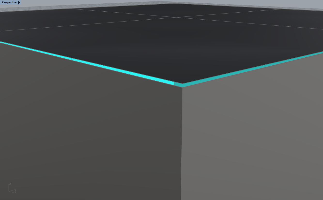
| Now, we can see which Surfaces are facing the wrong DIRECTION, before we join them together. We could select the surface highlighted in Cyan, and FLIP it, then select all of our Surface Geometry and JOIN it. By default, however, Rhino will attempt to find these unique surfaces, and FLIP them for you. This works with simple geometry, but not so much with complex geometry. If we attempt to JOIN all of our BOX Surfaces together, with (1) of the Surfaces FLIPped; Rhino will automatically flip the incorrect Surface for you- because a BOX is considered simple geometry. | 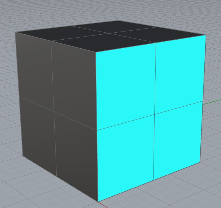 |
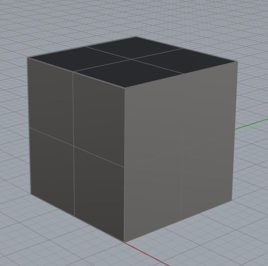
It is common for most 3D Modeling ‘Rookies’, to ignore file setup and options at the beginning of their files. Due to these ignored settings; Grid Snap is usually ‘OFF’, the Grid Options are typically ignored, and Object Snap is also ‘OFF’. When creating surface geometry with the hope to JOIN it all into a SOLID, this can be a big mistake. Solids are made of several surfaces joined together. Solids are also considered ‘watertight’, and closed off to the outside world. The BOX Geometry, on our BOX Layer, is completely Closed and watertight. There are no openings within this Geometry, in which ‘theoretical’ water or air could penetrate into the BOX. This is an attribute for all Solids, and for 3D Printing, it is essential.
By setting up your Grid Options, using Grid Snap, and using Object Snap; you can become a more proficient modeler for 3D Printing and various other realms. It is typical, that we ‘eyeball’, and ‘guess-timate’ where Surfaces begin and end; but the truth is: If our surface edges are not sharing the exact same point in space, your surfaces will not JOIN into a Valid Polysurface. When we build surfaces, or create new surface geometry, we must make certain that our Surface Edges are Manifold. If any edges are not meeting up exactly, then we will be left with an Open Polysurface. By using Grid Snaps, and Object Snaps, we can better determine how our surface is generated, in reference to its related counterparts. For example:
Select your BOX Geomtery
EXPLODE the BOX into individual Surfaces
Select the topmost surface, and turn Control POINTSON by pressing ‘F10’ on your keyboard.
Find and select any control point
Type MOVE into the Command Prompt
Type V into the Command Prompt (Vertical=Yes), Push ENTER
Type 0,0 into the Command Prompt, Push ENTER
Type 0.01 into the Command Prompt, Push ENTER
Turn Control POINTSOFF by pressing ‘F11’ on your keyboard
Select All BOX Geometry ‘CTRL+A’
Type JOIN into Command Prompt
Type WHAT into the Command Prompt
We’ve now edited the location of a single corner, on a single surface. It is precisely 0.01″ off, that is 1/100th. When we zoom out, we can’t even see that the surface is off, and it looks like good geometry. But when we type ‘WHAT’ into the Command Prompt, we find that we have a Valid Polysurface, and that it is NOT solid (See Screenshot). The Edge tally indicates that we have (10) Manifold Edges, and (4) Boundary Edges. Boundary Edges indicate that the Surface Edge is not aligning with another edge, but it exists. In other scenarios, we may find ‘Non-Manifold’ Edges; this indicates that there are Surface Edges that are not aligning with other Surface Edges, but they are attempting to. Regardless of the scenario, you must patch, build, edit, or create surfaces to close off these open areas, and eliminate all Boundary/Non-Manifold Edges to create a Valid Solid Polysurface.
Next Recommended Tutorial: Creating Surfaces from Curves
END
Created by: P. Zach Ali
Date: 10.17.2013
[…] Next Recommended Tutorial: Valid PolySurfaces #Solids […]
[…] begin, we know that a Valid Polysurface, that is Solid, has (2) strict […]