This Tutorial references the following Rhino File: 3DP_Prep.3dm (All Layers should be OFF)
Rhinoceros defines Surfaces with Curve Geometry moving in the ‘U’ and ‘V’ Direction, called ‘Iso-Curves’. These Iso-Curves can be duplicated, edited, & adjusted so long as the User knows how to extract them. After editing Iso-Curves, a User can re-create the original Surface with the new, defining Iso-Curve Geometry.
To begin, there are several ways we can create Curve Geometry (without plug-ins). We will discuss some of the more common, and fundamental methods in Rhino. Regardless of the method, it is important to understand: the more curves you have to define a surface, the more control you have over the way it looks. Alternately, less curve geometry will still define a surface, but leave some of the work to the programming side of Rhino. Turn the ‘SURF’ Layer ON, and expand your PERSPECTIVE Viewport.

You should have a gray surface, with no curves on this Layer. We will start by discussing methods that utilize Commands from the ‘Curve’ > ‘Curve from Objects’ Drop-Down Menu in Rhino.
| If you already have a Surface you would like to pull Curves from, you can do so in multiple ways. For example, let’s say that you want an interior curve, pulled from a surface. You could PROJECT a curve onto the Surface, but a more efficient manner might involve the ‘Extract Iso Curve’ Command. Type EXTRACTISOCURVE into the Command Prompt. When prompted to ‘Select Surface for isocurve extraction:’, Select the Gray Surface. Your mouse will allow you to browse across the Surface and choose where you would like your Iso-urve extracted from. Alternately, you have the option of pulling an Iso-curve in the opposite Direction: During the EXTRACTISOCURVE Command, (after you’ve selected your Surface) the Command Prompt indicates the Direction of the Iso-curve you are pulling. (Direction=U, See Fig. 1.3) | 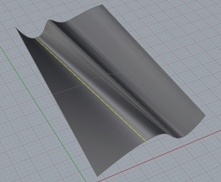 |

Fig. 1.3 : Type ‘D’ into the Command Prompt, Press ENTER, and the Direction of the Iso-curve you are attempting to create is changed from its previous selection state. (‘U’ -> ‘V’)
| If we want to Extract Curves from the borders, or edges of Surfaces, there are multiple commands. Let’s start with something simple: Type DUPEDGE into the Command Prompt and press ENTER. The Command Prompt will ask you to ‘Select edges to duplicate’; select all (4) Edges of the gray surface (Edges will highlight in Yellow). Press ENTER when finished. The (4) Curves remain highlighted as selected geometry, and you’ve duplicated each edge of your surface. They are single curves, and they are NOT joined together. Sometimes, you will need to JOIN this Geometry; I recommend typing JOIN, immediately after you’ve exited the DUPEDGE Command- this way, you won’t have to re-select each curve. The DUPEDGE Command is primarily for duplicating single edges. |  |
| If you need all the edges of a Surface, extracting the Border is also a possible method. Begin by getting rid of the Curve Geometry we’ve created thus far. Type SELCRV into the Command Prompt and then DELETE all your Curve Geometry. Next, Type DUPBORDER in the Command Prompt and Press ENTER. Select the gray surface, and the entire border will highlight in yellow. Press ENTER to exit the Command. You’ve extracted the entire border of a Surface, and the Edge Curves are joined. We could accomplish the exact same task by duplicating all (4) edges, and JOINing them afterward; but, this is a more efficient manner of Duplicating Edge Curves. Before continuing, delete all of your Curve Geometry: SELCRV & DELETE |  |
| You have to be careful when using the DUPBORDER Command. Sometimes, you won’t have a single surface with (4) Edges; follow these instructions: Make your TOP Viewport Active. Type CIRCLE into the Command Prompt; type 4,4 to indicate the Circle Center Point, and press ENTER. Type 2 to indicate the Circle Radius, and press ENTER. Next, Type TRIM into the Command Prompt; when prompted to ‘Select cutting objects’, select the Circle and Press ENTER; when prompted to ‘Select object to trim.’, Select the surface on the interior of the circle and Press ENTER. Make your PERSPECTIVE Viewport Active. This will trim away a circular sized portion of your geometry. You should now have a surface that resembles Fig 1.6. | 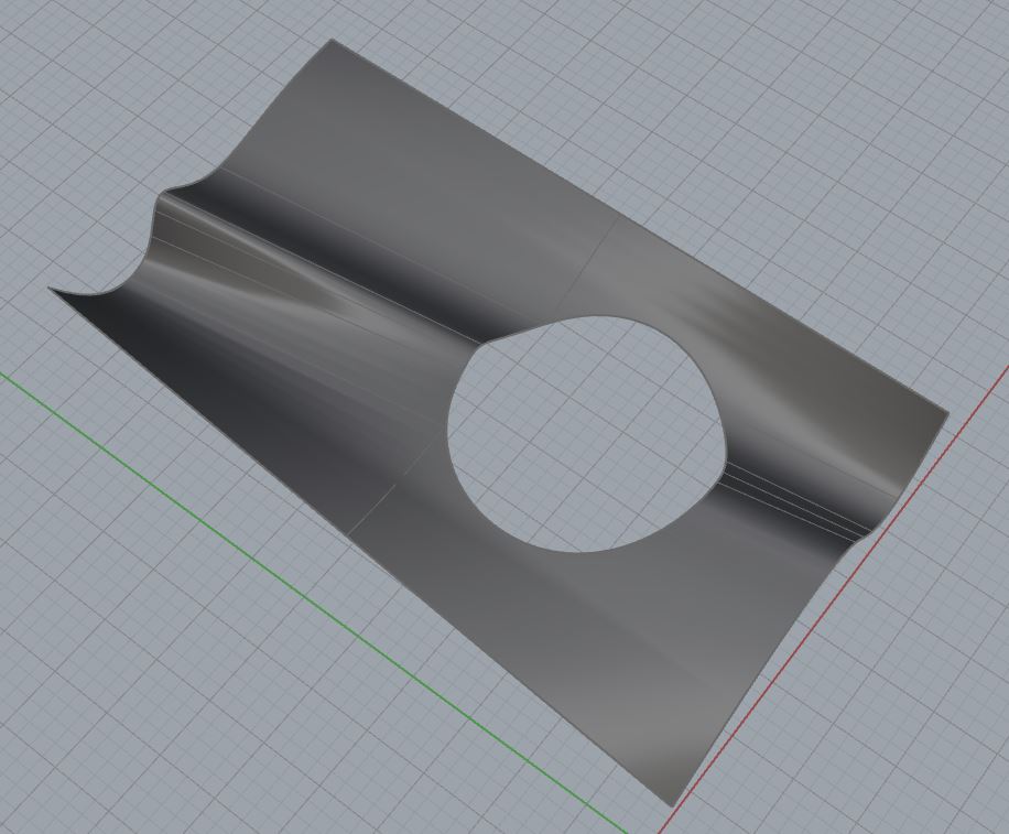 Fig. 1.6 Fig. 1.6 |
| Next, Duplicate the Surface Border by typing DUPBORDER into the Command Prompt, then press Enter. You should see a highlighted yellow border around the outside of your surface, and on the inside circular portion, as indicated in Fig. 1.7. This is fine if that is your ultimate goal; however, it is usually the case that we do not want that inside curve. We could, very simply delete the Circular Curve Border, but 3D Modeling & Digital Fabrication is about efficiency. What if we had several circles? Would we select multiple circular curve segments and delete them? The answer is up to you, but a more efficient manner of extracting a curve border from a surface that has interior borders, involves another command called ‘Duplicate Face Border’. Type SELCRV into the Command Prompt, and DELETE your Curves. | 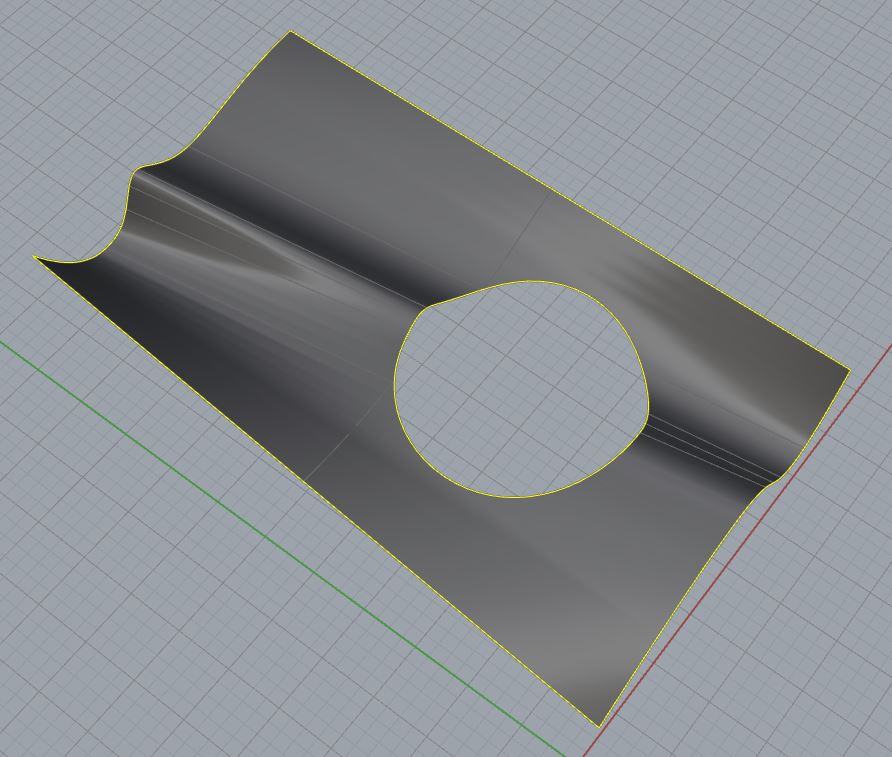 Fig. 1.7 Fig. 1.7 |
| Duplicating a Face Border will extract the Exterior Surface Edges, rather than all borders. Type DUPFACEBORDER into the Command Prompt, then select your Surface. Press ENTER. You will extract the Surface Edges as indicated in Fig. 1.8. This eliminates the time involved with deleting any interior Curve Borders. Furthermore, ALL of these CURVE FROM OBJECT commands allow a user to extract Surface Edges as Curves. These Curves are what defines a Surface. You can edit these Curves as much as you like, by turning on your control points and adjusting the Control Point Locations. To turn on Control Points, Press the F10 Key (POINTSON) and select your geometry. The points that appear are capable of being dragged and edited. F11 (POINTSOFF) will turn your Control Points off. Once adjusted to your preference, you can re-create the Surface with Surface from Curve Commands. | 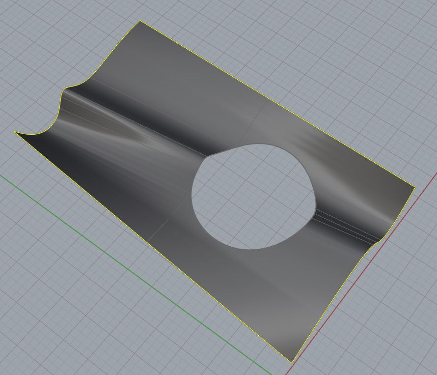 Fig. 1.8 Fig. 1.8 |
Next Recommended Tutorial: Creating Surfaces from Curves
END
Created by: P. Zach Ali
Date: 10.21.2013