This Tutorial references the following Rhino File: Drilling.3dm (All Layers should be OFF)
RhinoCAM is a Computer Aided Machining Plug-in for Rhinoceros 3D. There are various types of Operation Categories, such as 4-Axis, 3-Axis, 2.5-Axis, and Holes. ‘Drilling Operations’ fall in the ‘Holes‘ Category. This Tutorial discusses Drilling Operations.
Drilling Operations can be used for several applications; through-holes, tapping, counter-sinking, etc. Though the applications may have their subtle differences, especially with regard to their Traditional vs. Non-Traditional uses; the Geometry Requirements and Operation Parameters typically remain constant. Begin by turning your ‘DRILL’ Layer ON, & your PERSPECTIVE Viewport Active.
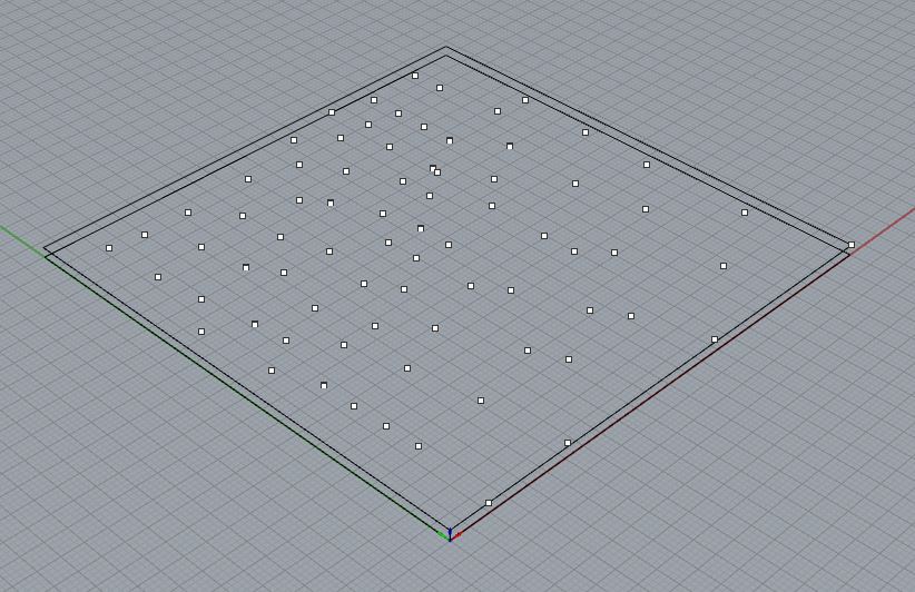
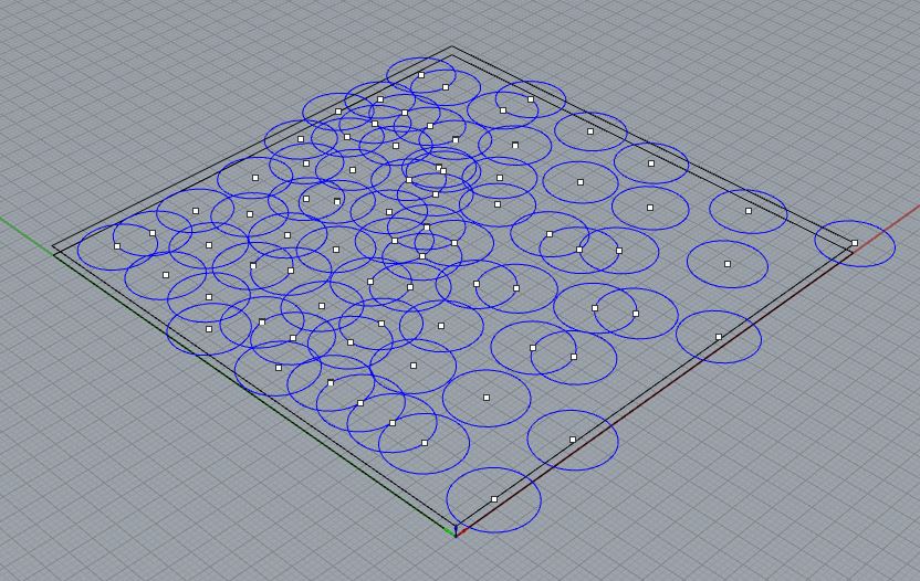
Drilling Operations require CIRCLE, or POINT Geometry. There are other possible geometry options, but we will only discuss the Geometry that maintains efficiency throughout the workflow. CIRCLE Geometry can be created, or duplicated from existing Surface Edges with the DUPEDGE or DUPBORDER Commands. POINTS can be placed very easily, if there are existing reference points; such as the center of a CIRCLE, or the ENDPOINT of a CURVE. POINTS are also easier to select, compared to CIRCLE Geometry. The Select Points Command (SELPT) allows a User to easily find and Select all POINTs that exist within a Layer that is ON, assuming there aren’t any POINTs that are hidden. When RhinoCAM Processes this Geometry, it utilizes the Centerpoint of a CIRCLE, or the location of a POINT, to determine where the Tool Center Point (TCP) should plunge into your material. It is also useful to organize Drilling Geometry onto layers, for eventual ease of re-selection.
Drilling Operations can be used for drill holes, counter-sunk holes, through holes, & tapped or bored holes. Traditionally, Drilling is utilized for Functional Applications. Non-Traditional Methods are encouraged, however, only after you’ve a firm grasp on the fundamentals of Drilling Operations and Parameters. An example of each, Traditional vs. Non-Traditional, is provided below.

Fig. 1.3 Example of Non-Traditional Drilling Operations, whereas ‘Drilling’ is used as a means of aesthetic improvement.
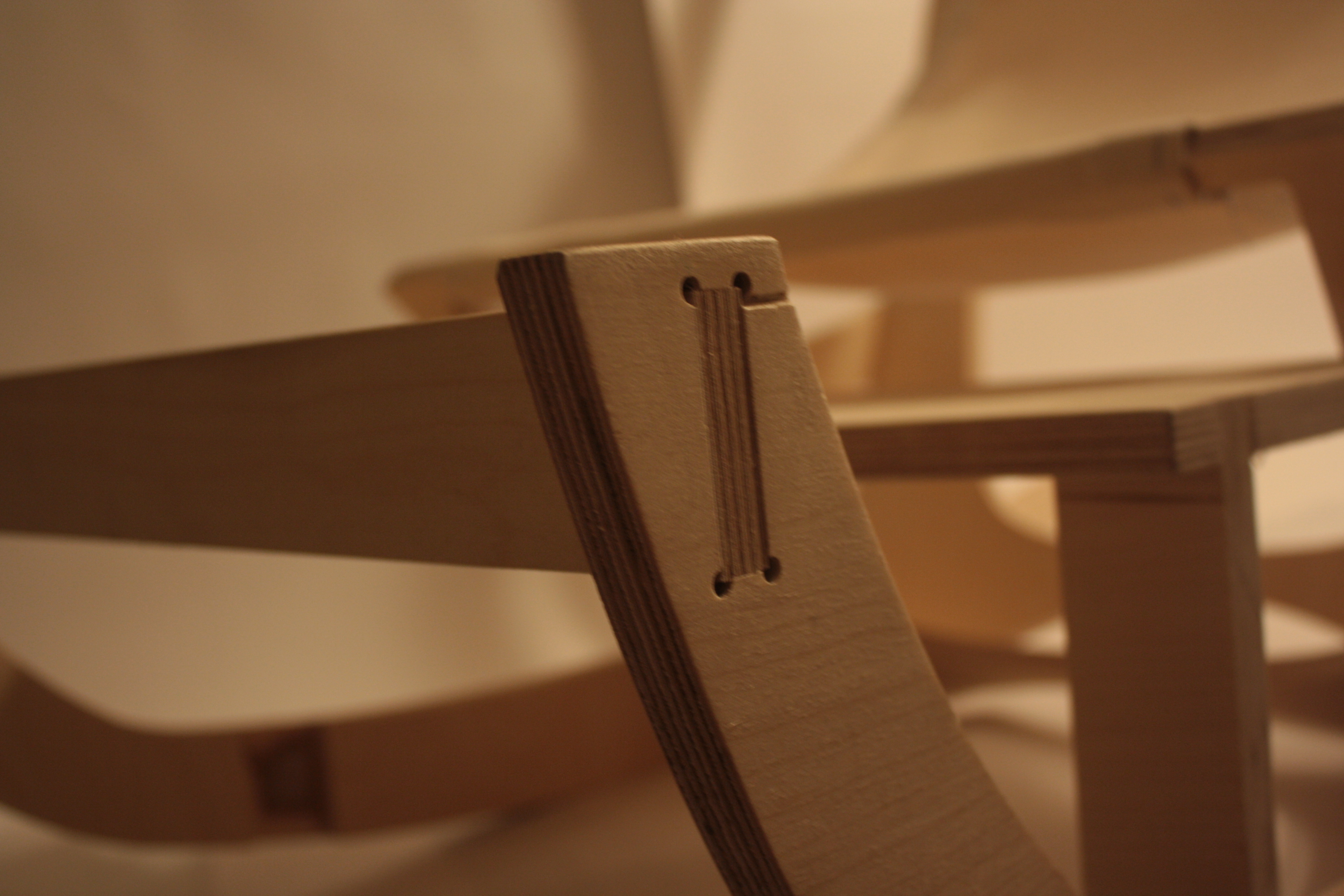
Fig. 1.4 Example of Traditional Drilling Operations, in which ‘Drilling’ is utilized primarily as a functional means.
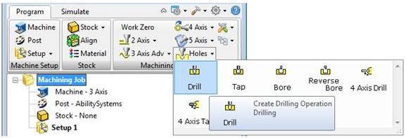
Find the RhinoCAM drop-down menu near the top of your screen. Find and Select your ‘Machining Operations Browser’. Make sure you have (1) of your geometry layers ON. Find and Select the ‘Holes’ Category within the Machining Operations Area of your Machining Operations Browser, this will expand into a new window, allowing you to select an Operation. Select the ‘Drill’ Operation.
| When selecting any operation, a new window will appear. This window will allow you to input and adjust all Operation affiliate parameters and options. The first window always asks for you to select geometry that will define the toolpath. This can be a ‘Region’ that restricts an operation to a specific area; it can be ‘Drive’ Geometry that an Operation uses for Location and Definition Purposes; or it can be a ‘Feature’, that RhinoCAM uses to determine where the toolpath should focus.In this scenario, we are selecting Drill Points, or Circles to define the toolpath. This is considered ‘Drive’ Geometry. Find and Select the Button labeled ‘Select Drill Points/Circles’. This will return you back to your Rhino Viewport to select your Drill Points or Circles that are affiliated with your Drilling Operation. If you have your Points or Circles organized onto layers, you can right-click on a layer, and ‘Select Objects’. Alternately, if you are using Point Geometry; you can type SELPT into the Command Prompt, and this will select all visible points.Press ENTER once you’ve selected your ‘Drive’ Geometry to return back to the Operation Parameters window.You should see a list of objects on the left side of your window. This is your ‘Drive’ Geometry Selection List. If you must, you can remove geometry from the list by selecting any object, and choosing the ‘Remove Active’ Button. Also, you can remove all geometry by selecting the ‘Remove All’ Button near the bottom of your screen. | 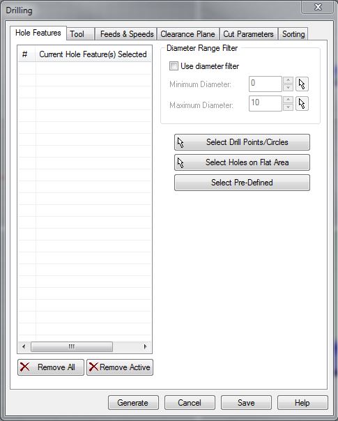 |
| Browsing to the ‘Tool’ Tab, allows you to select a Tool from the loaded Tool Library. This Tool Library is defined by dFAB Management, and changes often. This Tool Library is a Digital Simulation of what is available in the CNC Router’s Tool Library; it is important that you have the correct tool library loaded for successful completion of your operation. The Tool Libary for RhinoCAM is available for download here.When preparing a Drilling Operation, the Tool Tab will only allow you to select tools that have been designated as Drilling Tools. Milling Tools are created to cut primarily in the ‘X’ & ‘Y’ Directions, with minimal cutting in the ‘Z’ Direction. Therefore, we must use Tools that are designated for the repetitive ‘up and down’ motions a Drilling Toolpath requires. If you require a specific Drilling Tool Diameter, speak with dFAB Staff to determine your best course of action. Otherwise, select a tool, and continue. | 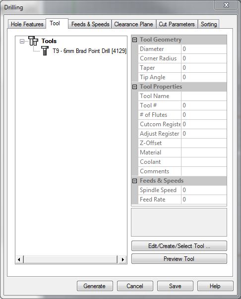 |
| Feeds & Speeds indicate the Feed Rate in which the Tool moves throughout an operation; and the speed in which the Tool rotates throughout an operation. Feeds and Speeds are dependent upon several factors, including Material Selection, Bit Selection, and Operation Selection. For example, if we are cutting into foam, our Feeds and Speeds could increase; compared to cutting into a Lumber Product, where our Feeds and Speeds must decrease. If our Bit Selection has a larger diameter (vs. Smaller Diameter), the Feeds and Speeds increase, because larger diameter tools can handle a heavier load. If our Operation is a Finishing Toolpath, our Feeds and Speeds can increase, because Finishing Passes involve cutting away minimal amounts of material. A Roughing Operation is primarily used for cutting away large amounts of material, and would have slower feed rates as a result.Feeds and Speeds also depend on the Milling Tool’s: Physical Properties, Diameter, Flute Count, Length, Feed/Tooth etc. In short, Feeds and Speeds are difficult to determine, and remember. dFAB has some of the more common Feed Rates posted here. Simply input the values that correspond with your: Operation Selection, Material Selection, and Bit Diameter. | 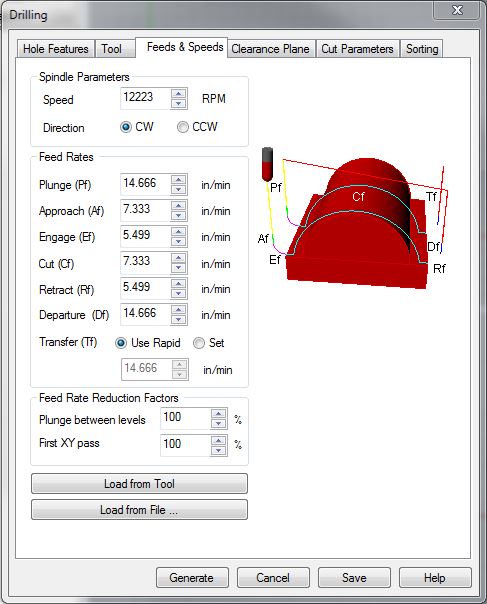 |
Spindle Speed
Spindle Speed indicates how many Rotations per Minute (RPM), a Milling Tool will complete. This value requires a delicate balance; where too many rotations or too few of rotations causes the bit to become overloaded with material chips and consequently dulls the tool.
Plunge
Plunge Values indicate how fast the Tool moves in downward ‘Z’ Axis Motions. This Motion may make contact with your materials. dFAB has limited this value to a MAX of (100) inches per minute. (ipm)
Approach
Approach Values indicate how fast the Tool moves during Entry/Exit motions. To extend Tool Life, we program Entry and Exit Motions, where the Tool can ‘Enter’ the Material at an Angle, or use a Radial Movement to begin tool paths; rather than Plunging directly into the Material. Approach Motions always occur after a Plunge Motion, or before a Retract Motion.
Engage
Engage Values indicate how fast the Tool is moving when 50% of the Diameter of the Cutting Tool is engaged in the material. This occurs very quickly, after an Approach Motion.
Cut
Cut Values indicate how fast the Tool is moving when 100% of the Tool Diameter is engaged in the material.
Retract
Retract indicates how fast the Tool is moving on upward ‘Z’ Axis Motions. This occurs when the Tool is retracting to its Clearance Plane, and does not make contact with the Material. Typically, we MAX these values. The CNC Router’s MAX Speed is 1000 inches per minute (ipm).
Departure
Departure indicates how fast the Tool is moving on the ‘X’ & ‘Y’ Axis, once it has reached its Clearance Plane. This occurs after the Tool has retracted, and should not make contact with anything within the CNC Work Area, so long as the Clearance Plane has been defined correctly.
| Your Clearance Plane is the height your Tool will utilize to perform Non-Cutting Operations and Movements. This is a ‘Safe-Height’ the Tool can reference after picking up a tool, or moving to a new Plunge Location. While your Clearance Height Settings will change when utilizing other CNC Equipment; in dFAB, you will ALWAYS set your Clearance Plane to:1. Find and Select the radio button Labeled ‘Absolute Z Value’2. Input the value ‘5’ into the field next to this Label and Button | 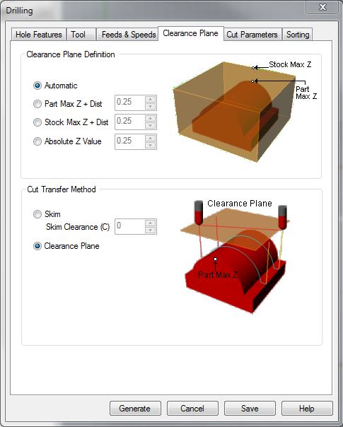 |
| This indicates that our Clearance Plane will always be 5″ above the Table. This will ensure that the Tool will NOT run into the Tools loaded in the Tool Library, as well as any materials that are loaded on the table. (The maximum thickness of material you can work with on this Equipment, is 5″) | 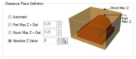 |
| Cut Parameters will indicate how your operation functions. For Drilling Toolpaths, we must input what type of Drilling Toolpath; the Depth we want the Tool to Drill, the Location of our Cut Geometry, and our Approach Distance. Drill Types You have the option of selecting from various Drilling Methods. For the sake of ease, we will discuss the two most common types: Standard Drill, and BreakChip Drill. Standard Drilling is a simple Drilling Motion; you indicate the Depth you want to drill, and it Drills to that depth. BreakChip Drilling will drill into the material at an incremental depth, retract back and out, then drill further than the previous drilling motion, retract back out; and it will repeat this process until it has reached the final depth you indicate. BreakChip Drilling offers extended Tool Life, and better results with materials. However, it also takes longer to complete. Standard Drilling is commonly used to improve final cut times. Depth Control This setting indicates how far the Tool should Drill into your material. This is measured from your Drive Geometry. Reference Location of Cut Geometry for further instructions. |
 |
Location of Cut Geometry
We will discuss (2) of the (3) options from this area. Selection ‘At Top’, indicates that your Drive Geometry is located at the ‘Top’ of your Stock. For example, if we are Drilling into 1/2″ material, and our Drilling Drive Geometry (Points or Circles) are located 1/2″ above the CPlane in Rhino; then our Geometry is ‘At Top’. This means that our Toolpath will start drilling from our Drive Geometry Location, and down to the previously indicated Depth Control: Drill Depth. ‘At Bottom’, indicates that your Drive Geometry is located at the ‘Bottom’ of your Stock. For example, if we are Drilling into 1/2″ material, and our Drilling Drive Geometry (Points or Circles) are located on the CPlane in Rhino (Z0); then our Geometry is ‘At Bottom’. This means that our Toolpath will start drilling from our previously indicated Depth Control: Drill Depth as a ‘Z’ height, and down to our Drive Geometry. Setting your geometry to the TOP of your stock is highly recommended.
Dwell
Dwell is not defined in our Post Processor. This should be left to ‘OFF’. Dwell controls how long the Tool should remain in a Drill Hole, before retracting. This is primarily used when drilling into aluminum, to clear out debris and chips.
Engage/Retract
Here, we set our Approach Distance. The default setting is fine, however, it is highly recommended that you set this value to: (Material Thickness)x(2).
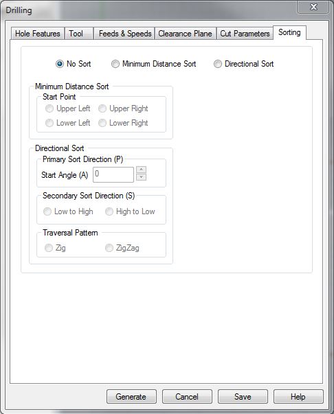
| When we browse to the Sorting Tab, we are selecting a ‘Sort’ Method for our Toolpath. This will improve your final cut time. If the Toolpath were to randomly select the order in which to Drill, or Mill geometry; we would have a disorganized, inefficient processing method. You have two options within this area. ‘Minimum Distance Sort’, or ‘Directional Sort’. Minimum Distance Sorting methods will drill or mill one piece of geometry first, before moving to the next closest Drive Geometry. Directional Sorting Methods, are used for more complex scenarios. For example, if we were milling a keyboard and chose Minimum Distance Sort, and we wanted to begin cutting from the letter ‘Q’; the next closest piece of geometry could be the letter ‘W’, or ‘S’, or ‘A’. Therefore, the Minimum Distance Sort Option, wouldn’t prove very useful. Directional Sorting, however, could control the Toolpath more efficiently. By choosing the Directional Sort Method, and indicating its Primary Sort Direction, Secondary Sort Direction, and Traversal Pattern; we can cut the letter ‘Q’, then move directly to the letter on the right, ‘W’. It would continue this Left to Right sorting method until the letter ‘P’, then move downward to the next letter, ‘L’, as its Secondary Sort Direction. Getting into the habit of selecting ‘Minimum Distance Sort’, at the very least, is highly suggested. |
 |
Next Recommended Tutorial: 2 Axis/2.5 Axis Tutorials
END
Created by: P. Zach Ali
Date: 10.30.2013