This Tutorial references the following Rhino File: 3DP_Prep.3dm (All Layers should be OFF)
After creating Surface Geometry, JOINing the Surfaces into one, Valid Polysurface will allow for successful 3D Printing Output. The ways we can build from our single Surface Geometry is infinite; this Tutorial discusses some of the more common methods.
To begin, we know that a Valid Polysurface, that is Solid, has (2) strict qualities:
1. The Surfaces must be facing the same direction.
2. The Surface Edges must be Manifold (Sharing the same location)
While building from your surface, you need to stay organized and pay attention to the smaller details. Setting up your Grid Snap Options, Grid Size, Rhino Units, and Object Snaps are all recommended. The better you model, the less work you encounter when preparing for 3D Printing. Turn the ‘CREATE’ Layer ON, and expand your PERSPECTIVE Viewport. Select the (5) Magenta Curves, and type NETWORKSRF into the Command Prompt. Press OK in the following window. Type SELCRV into the Command Prompt and Press ENTER. Type HIDE into the Command Prompt and Press ENTER. You should have a gray surface, without Curve Geometry appearing on this Layer.
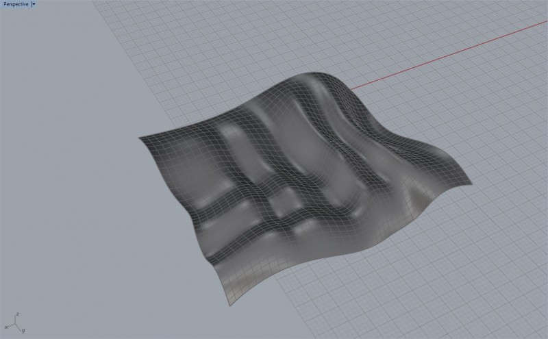
Let us assume that we want to 3D Print this Surface; to do so, we must have geometry that is considered Solid, and Watertight. Therefore, printing a single surface, or an Open Polysurface is unacceptable. We can build from this surface, possibly give it thickness, or continue building unique surfaces from it. We begin with something simple, giving the surface thickness. The Offset Surface Command works well for these scenarios, but we can discuss the Pro’s vs. Con’s as we move on. Select your Surface, and type OFFSETSRF into the Command Prompt. Press ENTER.
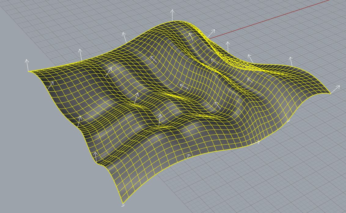
Fig. 1.1
You will see your Arrows projecting from your surface. This indicates the Direction in which the surface will offset towards. Before we continue, we should examine the Command Prompt, and the multiple options it provides a User when creating an Offset Surface.
![]()
When we examine the Command Prompt during the Offset Surface Command, there are several options that depict how our Surface will offset. Distance indicates how far your surface will offset. A value of (1) will create a Surface 1 inch (or whichever Units you may be using) away from your original Surface. Corner will create or maintain Sharp or Round Corners from the original surface. Solid will attempt to create a Closed, Solid Polysurface from your Offset by creating add’l Surface Geometry. Loose ensures that the resulting Offset Surface maintains a Surface Point Structure identical to the original Surface. Tolerance indicates the allowable deviation/change from the Original Surface to the Offset Surface. BothSides will create an offset surface on both sides of your original geometry. DeleteInput will delete the original Surface Geometry when the Command is completed. FlipALL will flip the Direction, or ‘Normal’ of the Surface, thus the direction in which the Surface will offset toward. The underlined letters in the Command Options, indicates the manner in which you might change the setting. For instance, Type ‘D’ into the Command Prompt, Press ENTER. Type ‘2’ into the Command Prompt, Press ENTER. This should reset the Distance to a value of: 2. Next, Type ‘S’ into the Command Prompt, Press ENTER. Your Solid Option should be set to ‘YES’. Press ENTER once these options are set.
| You should get a result similar to the image on the right. The surface has offset, and Surface patches have been created to ‘seal’ the Polysurface into a Solid. Unfortunately, the Offset Surface Command will offset as defined by the surface normals. Revisit Fig 1.1, we see the arrows pointing away from the surface in unique ways. This is the manner in which your surface will offset. Therefore, the OFFSETSRF Command, isn’t extremely useful for 3D Surfaces, nor is it functional with Polysurfaces. Let’s investigate another option. Undo the Offset Surface Command by Pressing CTRL+Z. You should only have the gray, Network Surface. | 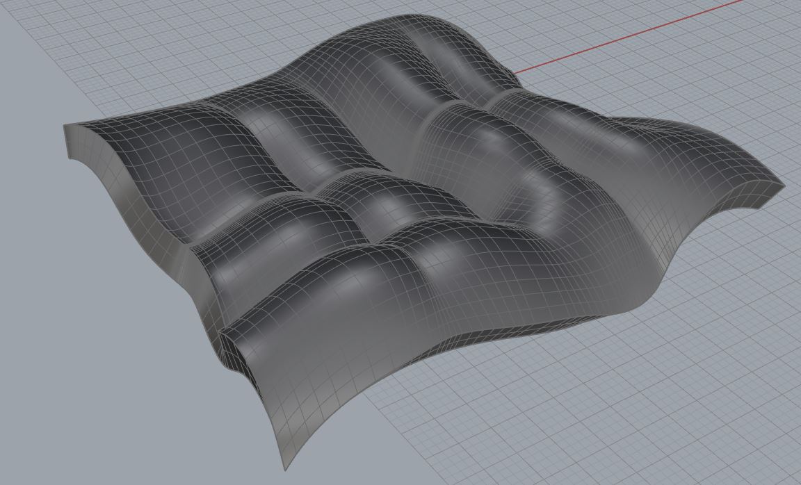 |
| Let’s continue working with the same surface. In our previous tutorial, we discussed Surface Creation through Curve Geometry. We can use these Commands and Methods with our current scenario. Begin by selecting your Surface, & Typing COPY into the Command Prompt, Press ENTER. Type ‘V’ into the Command Prompt, Press ENTER. Type ‘0,0’ into the Command Prompt, Press ENTER. Type ‘2’ into the Command Prompt, Press ENTER. Press ENTER once more to exit the COPY Command. This should leave you with (2) identical Surfaces, Offset 2″ away from each other. You should have something similar to the image on the right. | 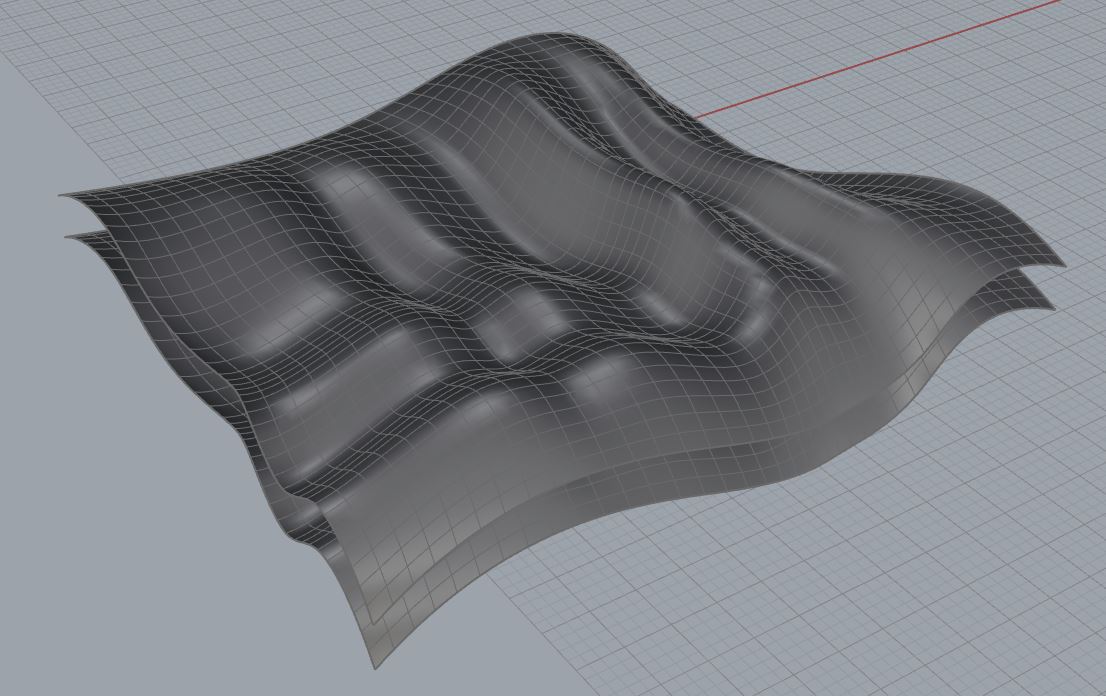 |
| We now have (2) identical surfaces that require Surfaces on the Edges. *Note, we could use the EXTRUDESRF Command to Extrude the Surface up or down; and in the process we would be left with a Solid Polysurface with Planar Edge Surfaces. See an example. However, if we want to make unique Surface Edges, we must define the Surface Edges with Curves. The image on the right clearly illustrates this example. We’ve drawn a Curve, between the ENDPOINTS of both Surfaces, and this will act as (1) of our Surface Edges. To gain even more control, we should define (3) more edges. | 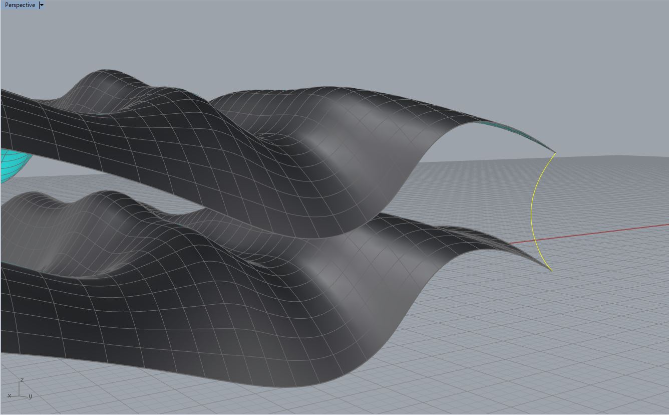 |
Fig. 2.3 Fig. 2.4
In Fig. 2.3, we’ve created another Edge Curve for the eventual creation of our Edge Surface. To create this Edge Surface, we need (2), (3), or (4) Curves. The more curves we have to define a Surface, the more control we have over the output. The EDGESRF Command can utilize Surface Edges as well as Curve Geometry to define a Surface. In Fig. 2.4, we Type EDGESRF into the Command Prompt and Press ENTER. Then we begin selecting our defining Iso-Curve geometry. We select our (2) Curves that we’ve created; and the (2) Surface Edges we would like to use for our Edge Surface. (Note: Fig. 2.4 illustrates (1) Edge Curve, and (2) Surface Edges selected, the 4th Curve has yet to be selected)
Once you’ve completed your selection, a new Surface is created. We can continue this Process around our entire Surface Edge to create (4) Total Surface Edges. It is important, that during this process, you use Surface Edges as defining Iso-Curve Geometry, as much as possible. You should also use your Object Snap, or OSNAP to snap any other Curve Geometry to Surface End Points. This will ensure that your Surfaces are tangent to each other, thus indicating Manifold Edges. Create your add’l surface edges to continue.
Let’s dicuss a few Surface Commands. Beginning with the JOIN Command. You can use JOIN with Surfaces, and Curves; but you should not use them for Solids. You JOIN Curves together to make them Closed, or for other specific tasks that may be related. You JOIN Surfaces together to make them Solid, or for other specific tasks that may be related. GROUPing and UNIONing is entirely different, and should not be used for these processes. When you JOIN several Surfaces or Curves together, the Command Prompt will indicate whether or not your Curves or Surfaces have JOINed into ‘Closed Curves’, or ‘Solid Polysurfaces’. You can use the WHAT Command, and this will present you with a window, describing in detail the status of your geometry. To UNDO JOINed Geomtery, you can use the EXPLODE Command. This will separate your Geometry into pieces. EXPLODE can be used with Solids, Surfaces, and Curves.
Other Commands that are typically confused, are TRIM & SPLIT. You should only use these commands with Surfaces, and Curves. You can use them with Solids, but you must make certain that you patch any openings that are left behind from this Command. We can expand on this subject and transition into Solid Editing Commands.
| On your CREATE Layer, start by making your TOP Viewport Active, & JOIN all of your Surfaces together. Select your JOINed Surfaces & Type WHAT to make sure that they have become a Valid, Solid Polysurface. Draw a CIRCLE above your Polysurface . The CIRCLE can be any size, so long as it does not extend outside of the Surface Boundaries. | 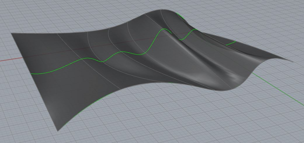 |
| Next, Type TRIM into the Command Prompt and Press ENTER. When Prompted ‘Select cutting objects’, Select your CIRCLE Geometry, and Press ENTER. When Prompted ‘Select object to trim’, Select any portion of your Polysurface that exists inside of the circle (Note: Only select the inner Polysurface Geometry once). Press ENTER and make your PERSPECTIVE Viewport active. Make sure you are in a Shaded Display Mode (CTRL+ALT+S) | 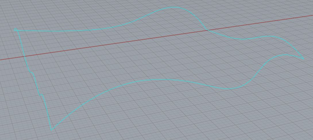 |
| When we inspect our Polysurface, we see that we have TRIMmed away a portion of the top Surface. This has now changed the state of our Geometry. It is no longer a Solid, Valid Polysurface- it is now just a Valid Polysurface. Because we have created an opening, our objects Volume is now infinite, and considered and open object. This will not work for 3D Printing output. We can fix this by creating more surfaces within this surface opening, and closing it off; but that is less efficient. Let’s assume that our goal was to make our object ‘Hollow’ on the inside. This would involve Boolean Commands, and working with Solids. Turn off your ‘CREATE’ Layer, and Turn on your ‘BOOLEAN’ Layer. | 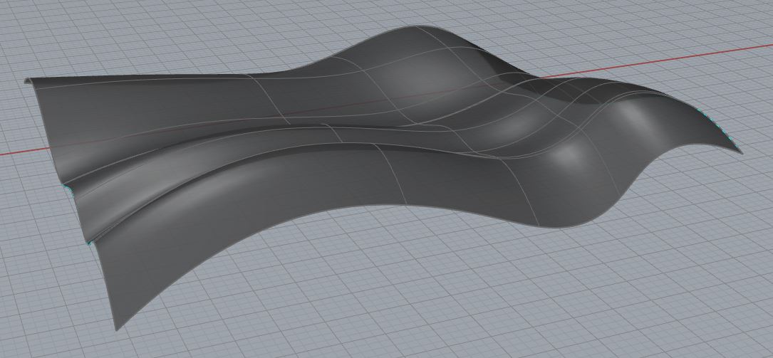 |
| Boolean Operations are specific to Solid Editing and Transformation. Your objects must be Solid, Valid Polysurfaces to use these Commands. | 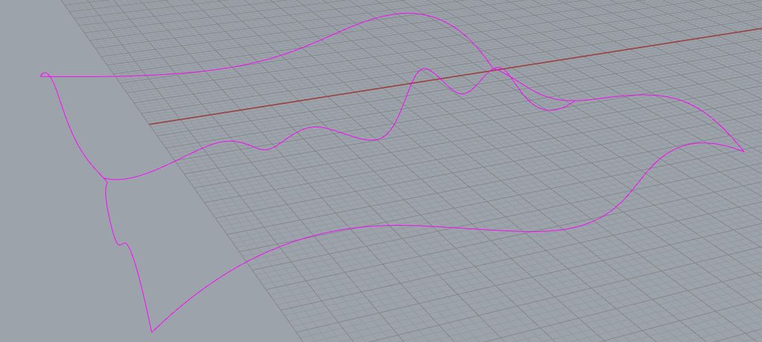 |
| The Command Prompt will read: ‘Select curves in network’. For your Network Surfaces to work correctly, there is a trick that tends to help more often than not: First, you must select the curves running in ONE Direction only. The image on the right shows you an example; each of the highlighted yellow curves is a Curve moving in the ‘V’ Direction. | 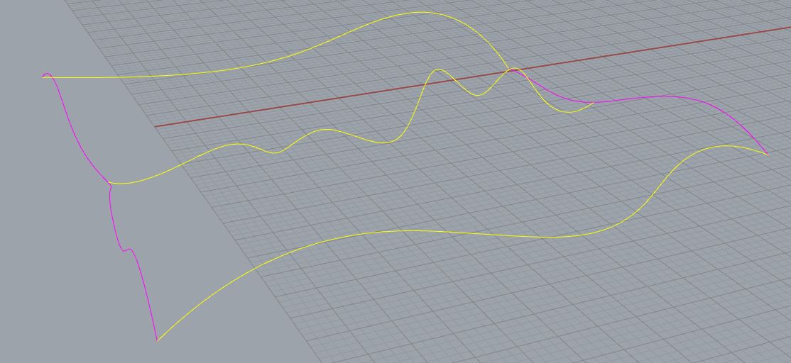 |
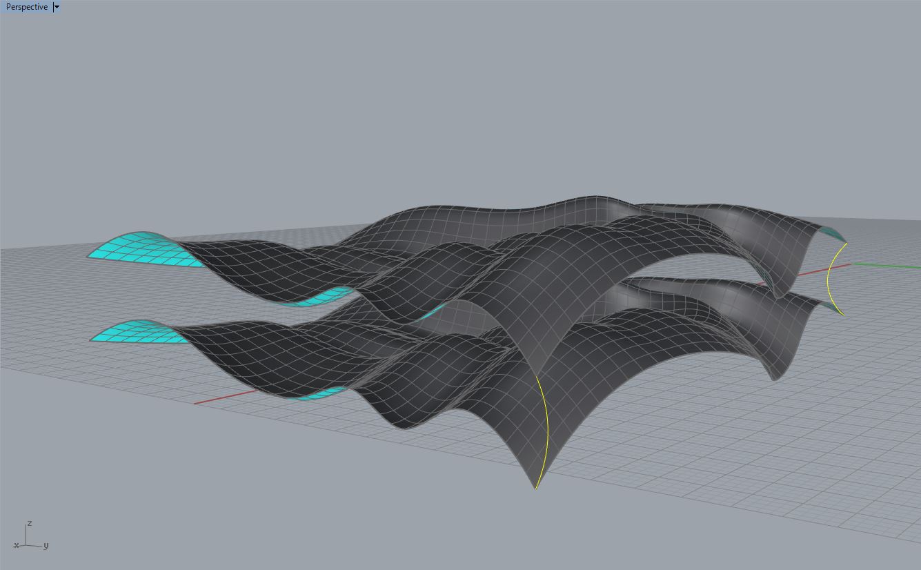
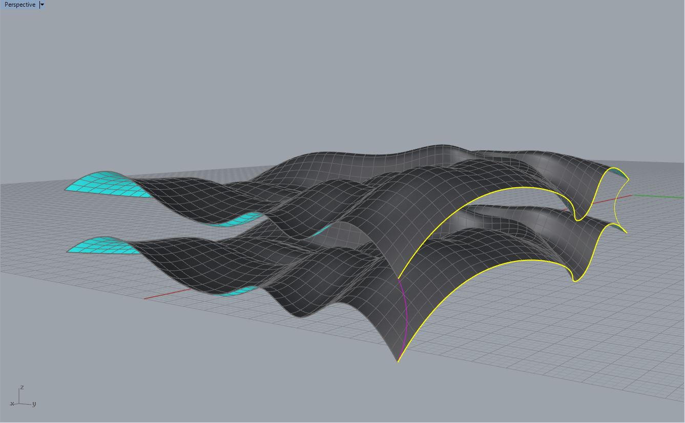
| Next, select the remaining curves running in the opposite direction. In this scenario, we only have (2) Curves running in the opposite direction (‘U’ Direction). The reason we select our Curve Geometry in this manner is because of the way Rhino processes the defining geometry. Rhino will attempt to ‘Automatically Sort’ your Curves; meaning, it will figure out which Curves are Edge Curves vs. Interior Iso-Curves. Rhino will figure it out if you have some basic Curve Geometry and just select it all at once; but there are scenarios in which your defining Curves are complicated, and Rhino may need some help figuring it all out. Press ENTER. | 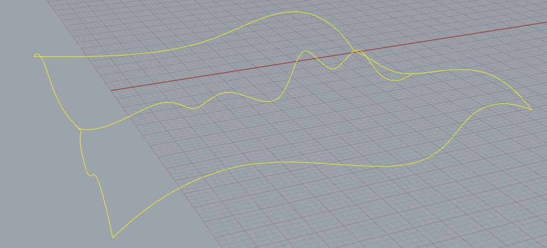 |
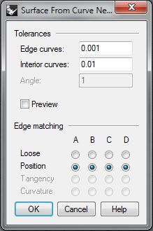 |
A window appears, titled ‘Surface from Curve Network’. Rhino will attempt to create your surface from the selected Curve Geometry; but sometimes, the curves are too complex or unique. To adjust the surface to the EXACT locations of all your defining Curve Geometry, you must indicate the allowable tolerances Rhino may adjust itself to. Edge Curves sets the allowable tolerance the surface may deviate from on your Edge Curves. Interior Curves sets the allowable tolerance the surface may deviate from on your Interior Iso-Curves. Edge Matching is a final area of options to adjust the Edges of your Surface to existing Geometry. Notice the A,B,C & D Labels; these correspond with your Surface Edges. If you look back to your Rhino Viewport, you will see your Edge Curves labeled with these Letters. You may adjust each edge separately from your options menu. Loose allows Rhino to ‘loosely’ adjust the Edges of your Surface to your Curve Geometry. Position attempts to maintain the Surface Edges as you have previously defined by Curve Geometry or Existing Surface Edges. Tangency is only available when one of your Surface Edges is ‘Tangent’ to another surface. If you are creating a Network Surface, and your ultimate goal is to JOIN these Surfaces into one Valid, Solid Polysurface- then it is HIGHLY recommended that you use Surface Edges as apart of your Curve Network- rather than Curve Geometry. Curvature options are rarely used, but typically involve cases where your defining Curve Geometry is square. |
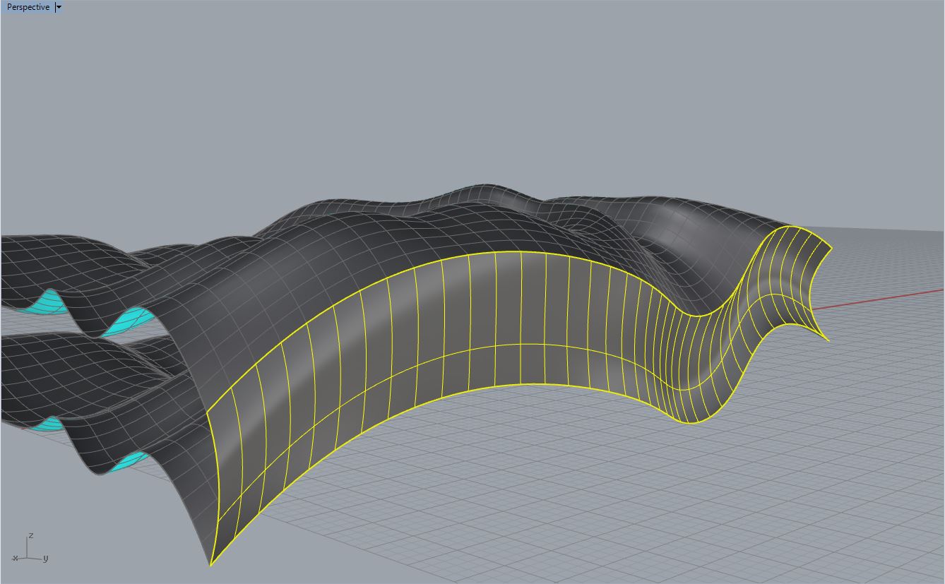
| Accept the default settings, and Press ENTER. The Options window disapears and leaves you with your final surface: A Surface, created from a ‘Network’ of defining Edge & Interior Iso-Curves, moving in the ‘U’ and ‘V’ Direction. This command gives you ultimate control over your Surface Creation, because you are defining surfaces in the exact same manner that Rhino defines a Surface. | |
Let’s dicuss a few Surface Commands. Beginning with the JOIN Command. You can use JOIN with Surfaces, and Curves; but you should not use them for Solids. You JOIN Curves together to make them Closed, or for other specific tasks that may be related. You JOIN Surfaces together to make them Solid, or for other specific tasks that may be related. GROUPing and UNIONing is entirely different, and should not be used for these processes. When you JOIN several Surfaces or Curves together, the Command Prompt will indicate whether or not your Curves or Surfaces have JOINed into ‘Closed Curves’, or ‘Solid Polysurfaces’. You can use the WHAT Command, and this will present you with a window, describing in detail the status of your geometry. To UNDO JOINed Geomtery, you can use the EXPLODE Command. This will separate your Geometry into pieces. EXPLODE can be used with Solids, Surfaces, and Curves.
Other Commands that are typically confused, are TRIM & SPLIT. You should only use these commands with Surfaces, and Curves. You can use them with Solids, but you must make certain that you patch any openings that are left behind from this Command. We can expand on this subject and transition into Solid Editing Commands.
Start by making your TOP Viewport Active, & drawing a CIRCLE above your Surfaces on your CREATE Layer. The CIRCLE can be any size, so long as it does not extend outside of the Surface Boundaries.
Next Recommended Tutorial: Surface to Solid
END
Created by: P. Zach Ali
Date: 10.22.2013
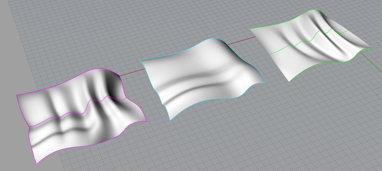
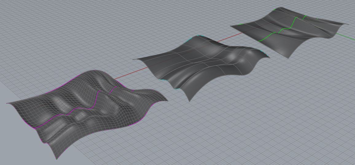
[…] Zoom out on your ‘CREATE’ Layer; if you’ve spent the time creating a Surface from Lofting, Edge Curves, and Curve Networking, you should see an example of each Surface in your Perspective Viewport. Try switching between Rendered and Shaded Viewports, and inspect the differences between each surface. Lofting offered minimal control over the output Surface. Edge Curves offered a little more control; but, Curve Networking offered the most control out of them all. You can see these differences just by looking at the Surfaces. Note: The Curves used to define each of these surfaces are all the same. Edge Curves Command utilized the (2) Edge Curves from the Lofted Surface; & the Curve Network Command used (2) Edge Curves from the Lofted Surface, (1) Interior Curve from the Lofted Surface, and (2) Edge Curves from the Edge Curve Surface. Ultimately, there was no deviation between the Curves, yet, with different commands, and more defining geometry, we created a more controllable output Surface. Next Recommended Tutorial: Surface to Solid […]