This Tutorial references the following Rhino File: 3Axis.3dm (‘STOCK’ Layer should be turned ON)
RhinoCAM is a Computer Aided Machining Plug-in for Rhinoceros 3D. There are various Operation Categories, such as 4-Axis, 3-Axis, 2.5-Axis, and Holes. ‘Parallel Finishing Operations’ fall in the ‘3-Axis‘ Category. This Tutorial discusses Parallel Finishing Operations.
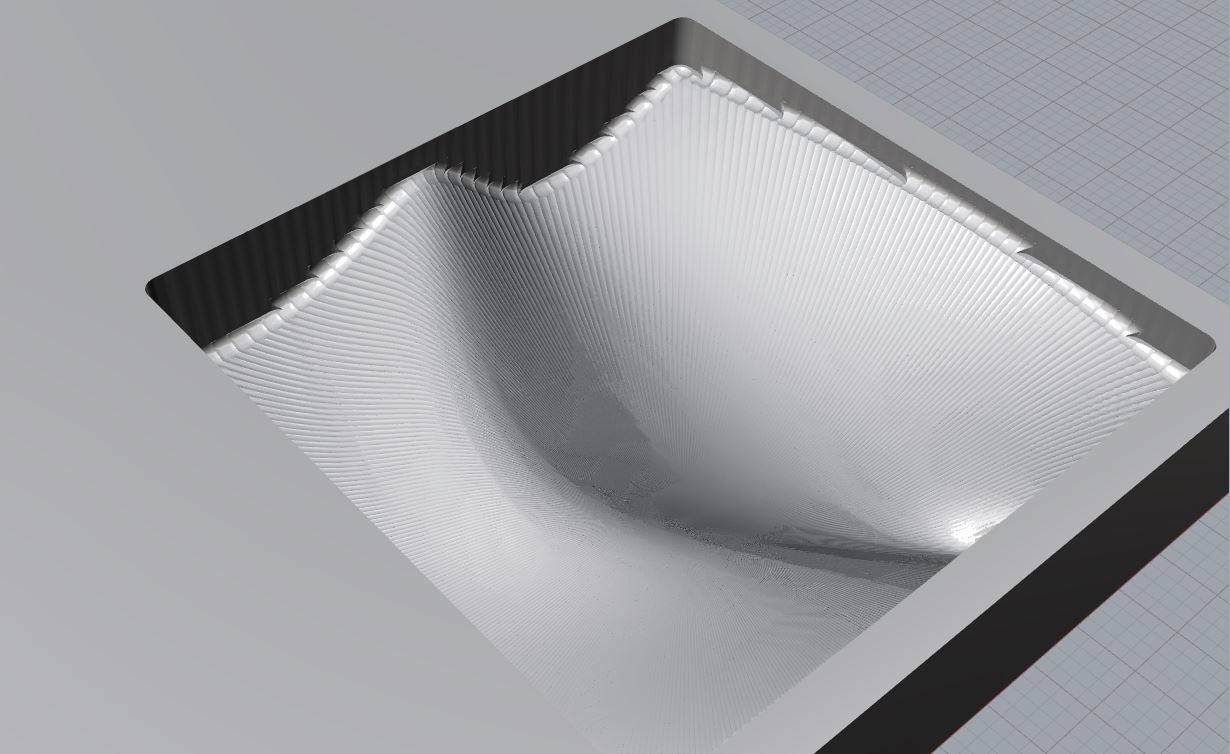
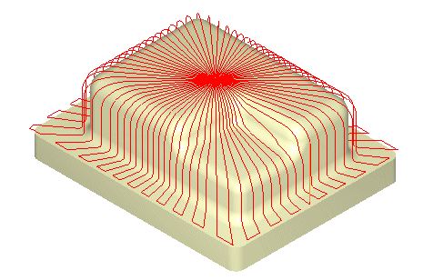
There are several CNC methods and/or operations utilized for ‘Finishing’ a Part. Radial Machining is one of the many finishing options of CAM Based Applications used in industry. Typically, Finishing Toolpaths are completed AFTER a Roughing Operation has completed. Finishing Toolpaths will provide you with a finer, more detailed final part- that more closely resembles your 3D Model. Specifically, Radial Machining Operations generate Toolpaths that ‘radiate’ from a defined ‘center-point’, across your Part’s Surface to restricting Surface Edges or Regions, and then return BACK to the defined ‘center-point’. Your ‘RM_PREVIEW’ Sub-Layer should give you a basic idea of how this Operation looks and functions.
Turn your ‘RM_PREVIEW’ Sub-Layer OFF; turn ON your ‘RADIAL MACHINING’ Layer. Parallel Finishing & other 3-Axis Operations, usually require Curve Geometry and Surface Geometry. Your Surface Geometry is used as the primary method of defining the operation. Finishing Passes, will use this Surface Geometry to determine allowable milling depths (‘Z’ Axis); Closed Curve Geometry will assist the Operation with defining ‘X’ & ‘Y’ Limitations. This is commonly referred to as a ‘Region’, and your Closed-Curve Geometry will restrict the Operation from leaving the ‘Region’ in the ‘X’ and ‘Y’ Direction.
Regarding Surface Geometry:
Surface Geometry is utilized to define the Toolpath, and furthermore restrict the Toolpath from Plunging into the Table. If you create a Surface, and the Surface features a ‘Hole’, leading to your Rhino C-Plane/Grid; the CNC Router will attempt to achieve that detail. Make sure you do not have any un-wanted ‘openings’ within your Surface Geometry. Additionally, you may notice there are no edges to our Surface Geometry: These Toolpaths are ‘3-Axis’ Operations, capable of cutting ‘X’, ‘Y’ & ‘Z’. The Operation cannot, and will not attempt to cut ‘underneath’ your surface, nor will it attempt to program toolpaths for anything it is incapable of reaching. These are commonly referred to as ‘Under-Cuts’. The best method of visualizing what a 3-Axis Operation can achieve, involves viewing your Parts, Surfaces, or Model- from a TOP View (Fig. 2.2). When we look at at TOP View, we cannot ‘see’ the underside of the Surfaces, therefore 3-Axis Operations cannot achieve these details.
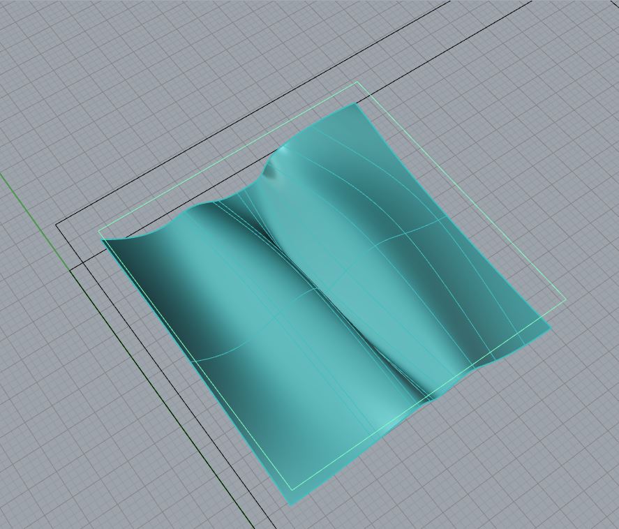

Fig. 2.2 TOP View of our Surface and Curve Geometry, required for 3-Axis Operations.
Regarding Closed-Curve Geometry:
Your Closed-Curve Geometry, also known as your ‘Region’; can exist anywhere in space- as long as the top-view clearly indicates the ‘X’ and ‘Y’ Limits. In Fig. 2.2, the highlighted Yellow Curve will act as our Region. Our Region will restrict the Toolpath to this specific area; and from a top-view, we can clearly see our bounding curves have no issues.
BACK TO TOP
ALL Finishing Operations, are Traditionally utilized to Finalize a 3-Dimensional Part after a Roughing Operation has completed. By completing a Finishing Operation, the part becomes more ‘finished’, and clearly indicates how the part should look once completed. This also allows a User to focus less on ‘Post Process’ Fabrication, such as Sanding, dusting, and any other additional Material Finishing Processes completed by hand.

Fig. 3.1 On some occasions, Finishing Operations are utilized in a manner that takes into account Post Processes such as Sanding. For example, EVERY Finishing Toolpath leaves behind ‘Scallops’- Scallops are ‘U’ Shaped results left-over from the Milling Process with a Ball-End Milling Tool. These Scallops are more prevalent when a large ‘Step-Over’ is programmed. A smaller Step-Over will eliminate the need for longer Post Processes, like Sanding. However, a smaller Step-Over also equates to longer Milling Times. Thus, the User must decide the most efficient work-flow: MORE Milling Time, and LESS Post Processing -or- LESS Milling Time, and MORE Post Processing. This decision is usually based on the selected Material, where Aluminum takes a LOT of time to Post Process, versus Foam, that may take a few minutes to sand smooth. Using Finishing Operations with Post Processes in mind, the User may Program a Finishing Operation to leave behind scallops that are easier to sand away. (i.e. Creating Parallel Finishing Toolpaths on a 45 Degree Angle)
In addition to the more common, Traditional uses of Finishing Toolpaths; dFAB encourages Non-Traditional Applications as well. Using a Finishing Toolpath with a large Step-Over, will improve Milling Times, and leave you with a Part that emphasizes the Toolpath utilized in the Milling Process. This can improve the overall look, aesthetic appeal, and emphasize the intent or inspiration of a final part. (i.e. Parallel Finishing for a more Linear Final Part, or Spiral Machining for a more Organic Final Part)
Find the RhinoCAM drop-down menu near the top of your screen. Find and Select your ‘Machining Operations Browser’. Turn OFF all Rhino Layers. Expand and Turn ON your ‘PARALLEL FINISHING’ & ‘STOCK’ Layers. Find and Select the ‘3 Axis Adv’ Category within the Machining Operations Area of your Machining Operations Browser, this will expand into a new window, allowing you to select an Operation. Select the ‘Parallel Finishing’ Operation.

| When selecting any operation, a new window will appear. This window will allow you to input and adjust all Operation affiliated parameters and options. The first window always asks for you to select geometry that will define the toolpath. This can be a ‘Region’ that restricts an operation to a specific area; it can be ‘Drive’ Geometry that an Operation uses for Location and Definition Purposes; or it can be a ‘Feature’, that RhinoCAM uses to determine where the toolpath should focus.In this scenario, we are selecting CLOSED Curve Geometry to define ‘Regions’. Your Regions will restrict the Finishing Operation from creating toolpaths in any location outside of the Closed Curve Geometry. With respect to your Regions, you should also make sure that you have Solid or Surface Geometry within your bounding Regions. Find and Select the Button labeled ‘Select Drive/Containment Regions’. This will return you back to your Rhino Viewport to select your ‘Regions’/Closed Curve Geometry. If you have your Geometry organized onto layers, you can right-click on a layer, and ‘Select Objects’. Select the Cyan (Turquoise) Closed Curve Geometry on the ‘PF_REGION’ Sub-Layer and Press ENTER to return back to the Operation Parameters window. A list of objects appears on the left side of your window. This is your ‘Region(s)’ List. If you must, you can remove geometry from the list by selecting any object from the list, and choosing the ‘Remove Active’ Button. Also, you can remove all geometry by selecting the ‘Remove All’ Button near the bottom of your screen. | 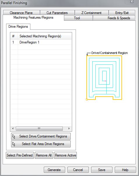 |
| Browsing to the ‘Tool’ Tab, allows you to select a Tool from the loaded Tool Library. This Tool Library is defined by dFAB Management, and changes often. This Tool Library is a Digital Simulation of what is available in the CNC Router’s Tool Library; it is important that you have the correct tool library loaded for successful completion of your operation. The Tool Libary for RhinoCAM is available for download here. Choosing the right Milling Tool for your Operation is dependent upon (4) Parameters: | 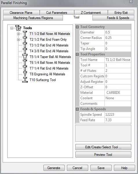 |
1. What Material you are Milling From
Dense Products, such as Lumber, Aluminum, Plastics etc; require more robust Milling Tools. Most Tools within the dFAB Tool Library are more than capable of Milling through these Dense Products- with the exception of a select few with the Label ‘FOAM ONLY’. These Tools do NOT have the same properties as the others, and should not be used for any other materials other than Foam. (The ‘FOAM ONLY’ Milling Tools are less expensive, this allows dFAB to direct the $savings$ to other items- like FREE double-sided tape) During this tutorial, let us assume we are milling from 3″ Thick Foam.
2. What Depth are you Milling to?
Your Material Thickness, and Milling Depth also play a roll in Tool Selection. If we plan on Milling all the way through 5″ Thick Lumber, then it is best to make sure there is a 5″-long Milling Tool in the dFAB Tool Library. Typically, the length of the Tool is also related to the Diameter. The LARGER the Diameter, the LONGER the Milling Tool, and vice-versa. During this tutorial, we are Milling from 3″ Thick Foam; it would be best if we found a Tool at least 3″ Long, just to be safe.
3. What Operation you are Preparing?
We know that we are preparing a Finishing Operation. Finishing Operations are utilized to remove the leftover material from a Roughing Operation, and leave the User with a nicely finished final surface. Ball-End Milling Tools are more commonly chosen for Finishing Operations.
4. What Detail do you require?
Tool Diameter normally will play a role with ALL Operations. It is commonly misunderstood that a SMALLER Milling Tool Diameter will provide a User with better Finishing Results. This is NOT entirely true. The 3-Dimensional part will indicate whether or not a Smaller Diameter Milling Tool is required. For example, in Fig. 5.2, a Part with a ‘V-Groove’ Detail is desired. Unfortunately, with a Ball-End Milling Tool, this detail is un-achievable. However, by using a Smaller Diameter Milling Tool, we can more closely achieve the desired detail. *Note: While greater detail may be desired, the User must also pay close attention to the Maximum Cutting Depth- as Smaller Diameter Milling Tools are most often shorter in length; in comparison to Larger Diameter Milling Tools that are LONGER in length.

During this tutorial, we require:
– ANY Tool: capable of Milling FOAM
– Ball End Tool: to provide a Smooth Finish
– Larger Diameter Tool: to remove Material faster, smaller details aren’t a primary concern
– (>= 3″) Length of Tool: accommodating our 3″ Thick Material & Cut Depths
– This narrows our selection: T1 – 1/2″ Ball-End Milling Tool seems to meet all criteria. Select this Tool and browse to the next tab.
| Feeds & Speeds indicate the Feed Rate in which the Tool moves throughout an operation; and the speed in which the Tool rotates throughout an operation. Feeds and Speeds are dependent upon several factors, including Material Selection, Bit Selection, and Operation Selection. For example, if we are cutting into foam, our Feeds and Speeds could increase; compared to cutting into a Lumber Product, where our Feeds and Speeds must decrease. If our Bit Selection has a larger diameter (vs. Smaller Diameter), the Feeds and Speeds increase, because larger diameter tools can handle a heavier load. If our Operation is a Finishing Toolpath, our Feeds and Speeds can increase, because Finishing Passes involve cutting away minimal amounts of material. A Roughing Operation is primarily used for cutting away large amounts of material, and would have slower feed rates as a result. Feeds and Speeds also depend on the Milling Tool’s: Physical Properties, Diameter, Flute Count, Length, Feed/Tooth etc. In short, Feeds and Speeds are difficult to determine, and remember. dFAB has some of the more common Feed Rates posted here. Simply input the values that correspond with your: Operation Selection, Material Selection, and Bit Diameter. | 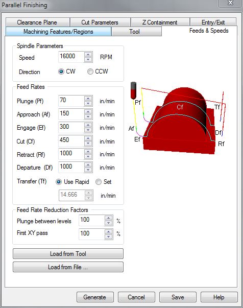 |
Spindle Speed
Spindle Speed indicates how many Rotations per Minute (RPM), a Milling Tool will complete. This value requires a delicate balance; where too many rotations or too few of rotations causes the bit to become overloaded with material chips and consequently dulls the tool.
Plunge
Plunge Values indicate how fast the Tool moves in downward ‘Z’ Axis Motions. This Motion may make contact with your materials. dFAB has limited this value to a MAX of (100) inches per minute. (ipm)
Approach
Approach Values indicate how fast the Tool moves during Entry/Exit motions. To extend Tool Life, we program Entry and Exit Motions, where the Tool can ‘Enter’ the Material at an Angle, or use a Radial Movement to begin tool paths; rather than Plunging directly into the Material. Approach Motions always occur after a Plunge Motion, or before a Retract Motion.
Engage
Engage Values indicate how fast the Tool is moving when 50% of the Diameter of the Cutting Tool is engaged in the material. This occurs very quickly, after an Approach Motion.
Cut
Cut Values indicate how fast the Tool is moving when 100% of the Tool Diameter is engaged in the material.
Retract
Retract indicates how fast the Tool is moving on upward ‘Z’ Axis Motions. This occurs when the Tool is retracting to its Clearance Plane, and does not make contact with the Material. Typically, we MAX these values. The CNC Router’s MAX Speed is 1000 inches per minute (ipm).
Departure
Departure indicates how fast the Tool is moving on the ‘X’ & ‘Y’ Axis, once it has reached its Clearance Plane. This occurs after the Tool has retracted, and should not make contact with anything within the CNC Work Area, so long as the Clearance Plane has been defined correctly.
| Within the Entry/Exit Tab, we control how our Milling Tool ‘Enters’ and ‘Exits’ the material. These settings are most useful in industry, primarily because they extend the Milling Tool-Life. While the settings aren’t entirely necessary for your needs, you can improve your cutting edges by programming a method of Entry. Note* Finishing Operations usually remove minimal amounts of Material, and consequently the finish remains constant so long as the correct Feeds & Speeds are set. Entry/Exit Motions for Hardwoods, or Metals might improve final surface quality- but are entirely unnecessary for Materials that do not have a ‘grain’ direction, or less-dense. | 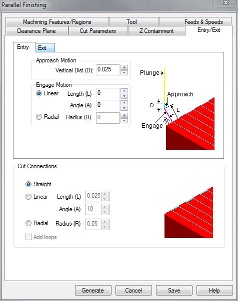 |
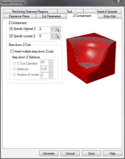
| Z Containment, controls the Milling Tool on the ‘Z’ Axis ONLY. Think of this tab as a ‘Machining Features/Regions‘ for your Z-Axis. Whereas our initial selected ‘Regions’ within the Machining Features/Regions Tab defined Milling Boundaries and Limits on the ‘X’ and ‘Y’ Axes; the Z Containment Tab defines Boundaries on the ‘Z’ Axis. By selecting the ‘Specify Highest Z’ & ‘Specify Lowest Z’ Checkboxes, we can define the highest & lowest ‘Z’ Values in the fields to the right. This will restrict RhinoCAM from creating Toolpaths outside of these bounds. These settings are typically unnecessary, as the highest & lowest ‘Z’ Values will default to your part’s Max & Min ‘Z’ Values- but it doesn’t hurt to get in the habit of activating and setting these fields. Our material thickness is 3 inches, therefore, our ‘Highest Z’ should be set to (3).RhinoCAM should never attempt to create toolpaths below ‘Z0’, so our ‘Lowest Z’ will always be set to (0). |
 |
| Within the Cut Parameters Tab, there are several settings considered ‘Default’, and consequently, we need not discuss their properties. Near the bottom of this window, however, we find our ‘STEPOVER CONTROL’. This Value controls how the Milling Tool Steps Over on the ‘X’ and ‘Y’ Axis. Previously discussed during the Horizontal Roughing Tutorial, ‘CUT LEVELS‘ controlled how our Milling Tool Stepped Down on the ‘Z’ Axis. With Finishing Operations, there isn’t a ‘Step-Down’ Value. The Milling Tool is programmed to follow the Surface/Solid Geometry within previously selected ‘Regions‘. Since the ‘Z’ Axis Movement is defined by the User Created Geometry- the Finishing Toolpath requires a Value to define how much the Milling Tool is allowed to ‘Step-Over’ on the ‘X’ & ‘Y’ Axes. Our Step-Over Value is dependent upon several factors: Milling Tools are typically engineered with specific properties that allow or enhance cutting capabilities. Properties such as Helical Cutting Angles, Flute Count, Material, Feed Rates, Diameter, and ‘Chip-Load’ all play a role in your Toolpath Settings. Our Toolpath Parameters are equally vast and difficult to remember. dFAB has posted some of the most common Feeds & Speeds, as well as Step-Down and Step-Over Values for your convenience. These settings apply to our Tool Library and Milling Tools ONLY; but it is a useful resource when learning how to prepare Milling Toolpaths. Keep in mind, a Finishing Toolpath is utilized to provide a User Defined quality of the final surface. | 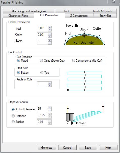 |
StepOver Control
| Our Step-Over, can be controlled by (1) of (3) ways: ‘%TOOL DIAMETER’; ‘DISTANCE’; or ‘SCALLOP’. ‘SCALLOP’ is not recommended, and will not be discussed during this tutorial. ‘% TOOL DIAMETER’ will program the Step-Over according to your selected Milling Tool’s Diameter. For example, if we were to select this option, and input (%50) into this field: 50% of 1/2″ Tool Diameter = 1/4″ (0.25″). Thus, our Step-Over would be 1/4″. Alternately, you may select the ‘DISTANCE’ Option, and input 1/4″ (0.25). | 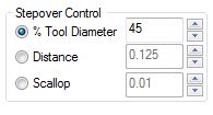 |
Simplified:
(Smoother Finish Quality) + (Longer Milling Time) = Small Step-Over Value [<18% Tool Diameter]
(Medium Finish Quality) + (Medium Milling Time) = Medium Step-Over Value [18-25% Tool Diameter]
(Rougher Finish Quality) + (Shorter Milling Time) = Large Step-Over Value [>25% Tool Diameter]
NOTE! – A general rule applies to every Milling Tool, Operation, and CNC Processes: NEVER set your Step-Over to anything GREATER THAN 50% of the Tool Diameter. The Tools are NOT designed to incur this kind of Cutting Load. This is inefficient, bad for the Tool, and bad for your Material.
| Your Clearance Plane is the height your Tool will utilize to perform Non-Cutting Operations and Movements. This is a ‘Safe-Height’ the Tool can reference after picking up a tool, or moving to a new Plunge Location. While your Clearance Height Settings will change when utilizing other CNC Equipment; in dFAB, you will ALWAYS set your Clearance Plane to: 1. Find and Select the radio button Labeled ‘Absolute Z Value’ 2. Input the value ‘5’ into the field next to this Label and Button |
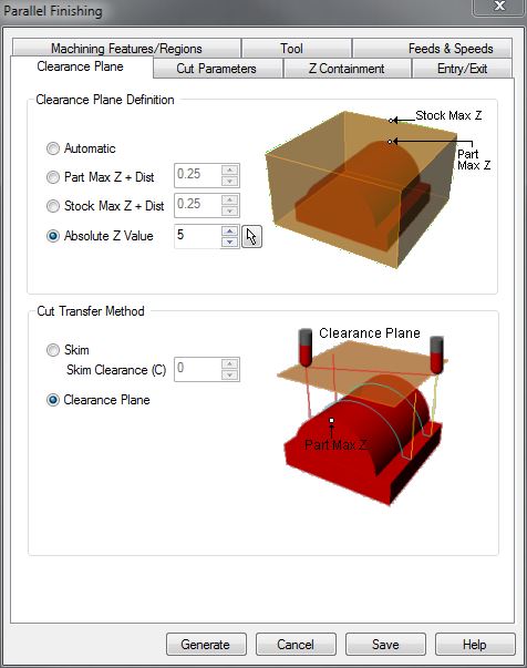 |
| This indicates that our Clearance Plane will always be 5″ above the Table. This will ensure that the Tool will NOT run into the Tools loaded in the Tool Library, as well as any materials that are loaded on the table. (The maximum thickness of material you can work with on this Equipment, is 5″) | 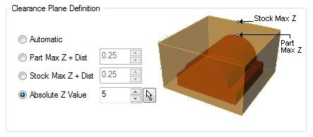 |
Next Recommended Tutorial: Other RhinoCAM Finishing Operations: Radial Machining, Spiral Machining, Between 2 Curves
END
Created by: P. Zach Ali
Date: 01.07.2014