This Tutorial references the following Rhino File: 2Axis.3dm (‘PART PREVIEW’ Layer & ‘ASSEMBLED’ Sublayer should be turned ON)
RhinoCAM is a Computer Aided Machining Plug-in for Rhinoceros 3D. There are various types of Operation Categories, such as 4-Axis, 3-Axis, 2.5-Axis, and Holes. ‘Profiling Operations’ fall in the ‘2.5 Axis‘ Category. This Tutorial discusses Profiling Operations.
Profiling Operations are more commonly utilized in functional applications. Typically, these operations are used to cut out parts and pieces that eventually fasten together. Simply put, Profiling will process parts by cutting on the inside, or the outside of a closed curve. An example of Profiled Parts, is visible on the ‘ASSEMBLED’ Layer. Let’s begin by taking a closer look at this example; turn ON your ‘EXPLODED’ Layer (located under ‘PART PREVIEW), & make your PERSPECTIVE Viewport Active.
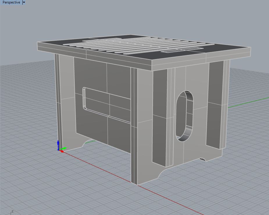
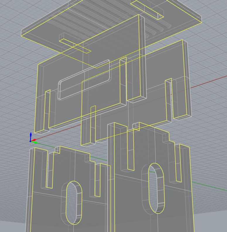
We see the Assembled Object, in an Exploded View; there are several areas on this final part that will not utilize Profiling Operations. However, the parts that are capable of being cut with Profiling Operations, will require specific geometry to be duplicated from these polysurfaces. Any Border Curves should be duplicated (DUPBORDER, DUPEDGE), and we will utilize these curves to cut out our pieces.
Profiling Operations require CLOSED, PLANAR Curves. Profiling can cut on the INSIDE, or the OUTSIDE of any CLOSED, PLANAR CURVE. An example of Inside versus Outside is provided on the IN VS. OUT Layer. Turn OFF your other layers, and turn ON the IN VS. OUT Layer. Make your RIGHT Viewport Active.

The Magenta (Pink) Curve is CLOSED, and PLANAR; if we were to cut out this piece with Profiling Operations, we would indicate that we would like to cut on the INSIDE of this Curve. The Blue Curve is also CLOSED, and PLANAR; and we would cut on the OUTSIDE of this Curve. Profiling Operations require that you create (1) Operation for cutting on the INSIDE, and a separate Operation for Cutting on the OUTSIDE.
Profiling, may be used for a variety of Applications; but is primarily used as a means of improving efficiency and work-flow within the Manufacturing Realm. Profiling Operations (also known as ‘Contouring), was one of the first Toolpaths created within the CNC Industry. This eliminated the need for Hand Routers, Table Saws, Band-Saws, Jig-Saws and other User Operated Equipment. While it has proven to be helpful when several parts require milling- a sense of understanding when to use this operation with CNC Operated Equipment versus when to use a Table Saw; is strongly encouraged. Users can become ‘less-efficient’, if they spend enough time preparing digital files; when they could easily cut a few parts with Analog Operated Equipment.
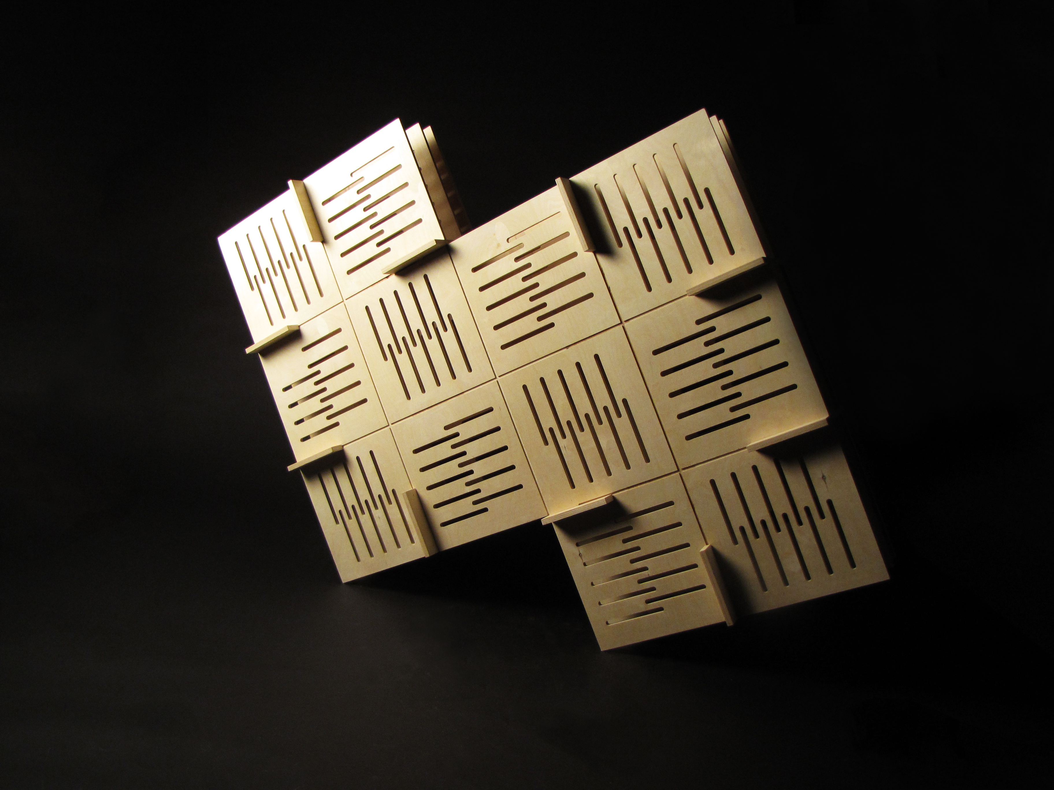
Fig. 3.1 Example of Profiling and Engraving Operations
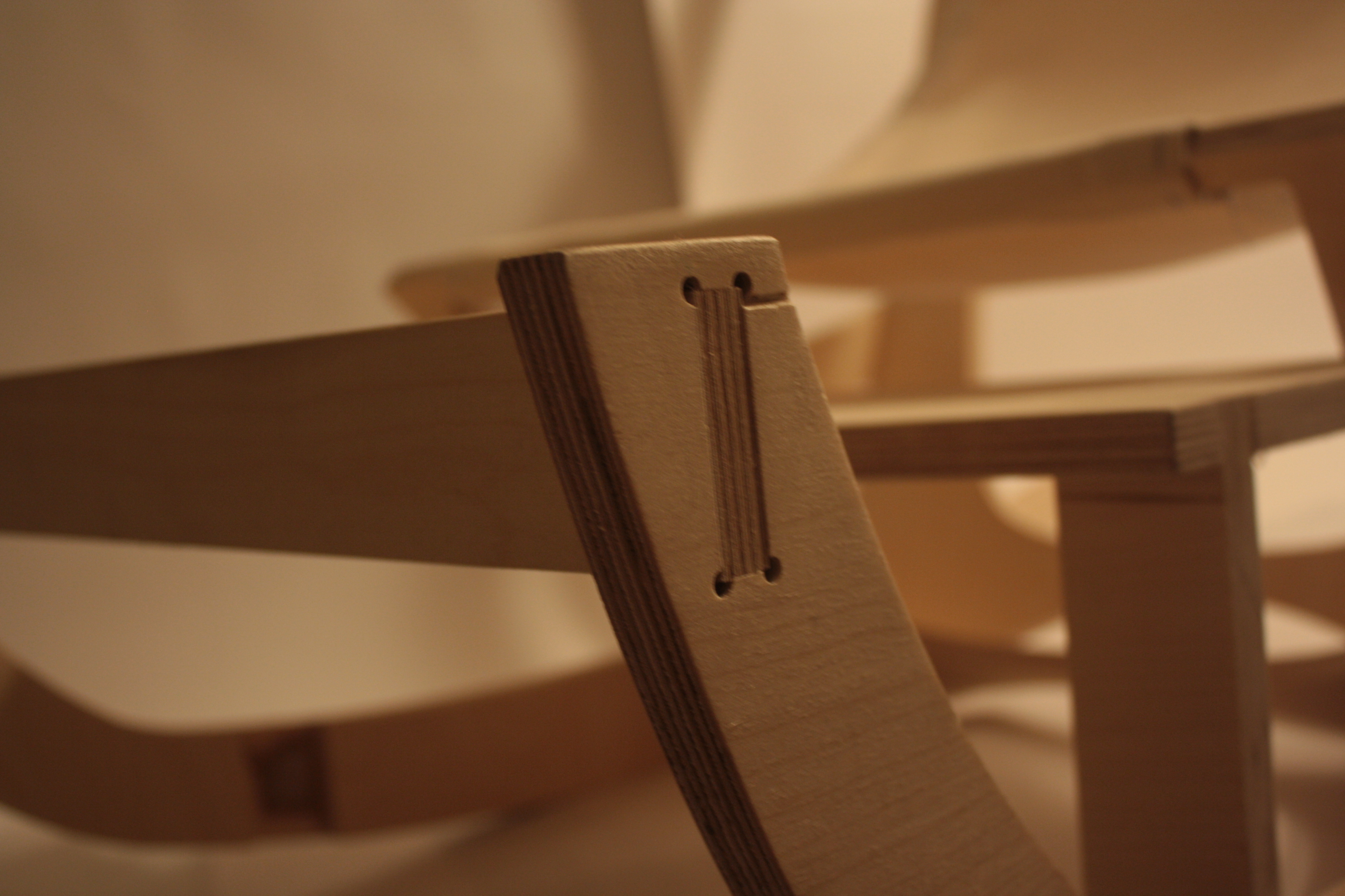
Fig. 3.2 Example of Profiling & Drilling Operations.
Find the RhinoCAM drop-down menu near the top of your screen. Find and Select your ‘Machining Operations Browser’. Turn OFF All Layers; Turn ON your ‘STOCK’ Layer; ‘OUTSIDE – GEOMETRY’ & ‘INSIDE – GEOMETRY’ [PROFILING TUTORIAL] Sublayers. Find and Select the ‘2 Axis’ Category within the Machining Operations Area of your Machining Operations Browser, this will expand into a new window, allowing you to select an Operation. Select the ‘Profiling’ Operation.
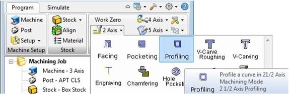
| When selecting any operation, a new window will appear. This window will allow you to input and adjust all Operation affiliated parameters and options. The first window always asks for you to select geometry that will define the toolpath. This can be a ‘Region’ that restricts an operation to a specific area; it can be ‘Drive’ Geometry that an Operation uses for Location and Definition Purposes; or it can be a ‘Feature’, that RhinoCAM uses to determine where the toolpath should focus.In this scenario, we are selecting Planar, Closed Curve Geometry to define the toolpath. This is considered ‘Drive’ Geometry. Find and Select the Button labeled ‘Select Drive/Containment Regions’. This will return you back to your Rhino Viewport to select your Profiling Drive Geometry. If you have your Geometry organized onto layers, you can right-click on a layer, and ‘Select Objects’. NOTE* You must create (1) Operation for Milling on the OUTSIDE of a Closed Curves, and a SEPARATE Operation for Milling on the INSIDE of Curves. We will discuss Profiling on the OUTSIDE of Curve Geometry during this Tutorial. Select All ‘Dark Blue’ Geometry on the ‘OUTSIDE – GEOMETRY’ Layer and Press ENTER to return back to the Operation Parameters window.You should see a list of objects on the left side of your window. This is your ‘Drive’ Geometry Selection List. If you must, you can remove geometry from the list by selecting any object, and choosing the ‘Remove Active’ Button. Also, you can remove all geometry by selecting the ‘Remove All’ Button near the bottom of your screen. |  |
| Browsing to the ‘Tool’ Tab, allows you to select a Tool from the loaded Tool Library. This Tool Library is defined by dFAB Management, and changes often. This Tool Library is a Digital Simulation of what is available in the CNC Router’s Tool Library; it is important that you have the correct tool library loaded for successful completion of your operation. The Tool Libary for RhinoCAM is available for download here. Choosing the right Milling Tool for your Operation is dependent upon (4) Parameters: |  |
1. What Material you are Milling From
Let us assume we are milling from 3/4″ MDF; this would indicate that we require a robust tool, capable of cutting lumber. Most tools in the Tool Library are more than capable, with the exception of a select few that are primarily designated as ‘FOAM ONLY’ Tools. Therefore, we have a relatively large selection.
2. What Depth are you Milling to?
Your Material Thickness, and Milling Depth also play a roll in Tool Selection. If we plan on Milling all the way through 5″ Thick Lumber, then it is best to make sure there is a 5″-long Milling Tool in the dFAB Tool Library. Typically, the length of the Tool is also related to the Diameter. The LARGER the Diameter, the LONGER the Milling Tool, and vice-versa. During this tutorial, we are Milling ALL the way through 3/4″ Thick MDF; it would be best if we found a Tool at least 3/4″ Long.
3. What Operation you are Preparing
We know that we are preparing a Profiling Operation. Profiling Operations are typically utilized to cut all the way through a Sheet of Material; therefore, we can rule out a few Milling Tool Selections such as Drilling and Engraving Tools. Ball End Tools will create a ’round’ bottom after milling through our material, and leave us with radius edges, rather than square edges. Thus, we can narrow our search, to any Flat End Milling Tool.
4. What Detail do you require?
We’ve come to the conclusion that we need a Flat End Milling Tool; but there are several different diameters to choose from. Consider the 90 Degree Corners you may be milling; because the Tool is round, we cannot achieve perfectly square Corners. Choosing a smaller diameter tool will certainly get you closer to a Square Corner, but also consider the trade-off of time. By utilizing a smaller diameter tool, your file will take longer to Mill. Determine whether or not the time you save by sanding away these corners is equal to the time you lose by using a smaller diameter milling tool.
During this tutorial, we will select the 3/8″ Flat Milling Tool. Simply select the tool, and browse to the next tab.
| Feeds & Speeds indicate the Feed Rate in which the Tool moves throughout an operation; and the speed in which the Tool rotates throughout an operation. Feeds and Speeds are dependent upon several factors, including Material Selection, Bit Selection, and Operation Selection. For example, if we are cutting into foam, our Feeds and Speeds could increase; compared to cutting into a Lumber Product, where our Feeds and Speeds must decrease. If our Bit Selection has a larger diameter (vs. Smaller Diameter), the Feeds and Speeds increase, because larger diameter tools can handle a heavier load. If our Operation is a Finishing Toolpath, our Feeds and Speeds can increase, because Finishing Passes involve cutting away minimal amounts of material. A Roughing Operation is primarily used for cutting away large amounts of material, and would have slower feed rates as a result.Feeds and Speeds also depend on the Milling Tool’s: Physical Properties, Diameter, Flute Count, Length, Feed/Tooth etc. In short, Feeds and Speeds are difficult to determine, and remember. dFAB has some of the more common Feed Rates posted here. Simply input the values that correspond with your: Operation Selection, Material Selection, and Bit Diameter. | 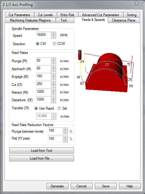 |
Spindle Speed
Spindle Speed indicates how many Rotations per Minute (RPM), a Milling Tool will complete. This value requires a delicate balance; where too many rotations or too few of rotations causes the bit to become overloaded with material chips and consequently dulls the tool.
Plunge
Plunge Values indicate how fast the Tool moves in downward ‘Z’ Axis Motions. This Motion may make contact with your materials. dFAB has limited this value to a MAX of (100) inches per minute. (ipm)
Approach
Approach Values indicate how fast the Tool moves during Entry/Exit motions. To extend Tool Life, we program Entry and Exit Motions, where the Tool can ‘Enter’ the Material at an Angle, or use a Radial Movement to begin tool paths; rather than Plunging directly into the Material. Approach Motions always occur after a Plunge Motion, or before a Retract Motion.
Engage
Engage Values indicate how fast the Tool is moving when 50% of the Diameter of the Cutting Tool is engaged in the material. This occurs very quickly, after an Approach Motion.
Cut
Cut Values indicate how fast the Tool is moving when 100% of the Tool Diameter is engaged in the material.
Retract
Retract indicates how fast the Tool is moving on upward ‘Z’ Axis Motions. This occurs when the Tool is retracting to its Clearance Plane, and does not make contact with the Material. Typically, we MAX these values. The CNC Router’s MAX Speed is 1000 inches per minute (ipm).
Departure
Departure indicates how fast the Tool is moving on the ‘X’ & ‘Y’ Axis, once it has reached its Clearance Plane. This occurs after the Tool has retracted, and should not make contact with anything within the CNC Work Area, so long as the Clearance Plane has been defined correctly.
| Your Clearance Plane is the height your Tool will utilize to perform Non-Cutting Operations and Movements. This is a ‘Safe-Height’ the Tool can reference after picking up a tool, or moving to a new Plunge Location. While your Clearance Height Settings will change when utilizing other CNC Equipment; in dFAB, you will ALWAYS set your Clearance Plane to: 1. Find and Select the radio button Labeled ‘Absolute Z Value’ 2. Input the value ‘5’ into the field next to this Label and Button |
 |
| This indicates that our Clearance Plane will always be 5″ above the Table. This will ensure that the Tool will NOT run into the Tools loaded in the Tool Library, as well as any materials that are loaded on the table. (The maximum thickness of material you can work with on this Equipment, is 5″) | 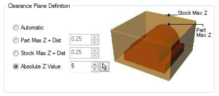 |
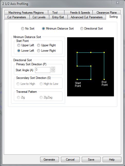
| When we browse to the Sorting Tab, we are selecting a ‘Sort’ Method for our Toolpath. This will improve your final cut time. If the Toolpath were to randomly select the order in which to Drill, or Mill geometry; we would have a disorganized, inefficient processing method. You have two options within this area. ‘Minimum Distance Sort’, or ‘Directional Sort’. Minimum Distance Sorting methods will drill or mill one piece of geometry first, before moving to the next closest Drive Geometry. Directional Sorting Methods, are used for more complex scenarios. For example, if we were milling a keyboard and chose Minimum Distance Sort, and we wanted to begin cutting from the letter ‘Q’; the next closest piece of geometry could be the letter ‘W’, or ‘S’, or ‘A’. Therefore, the Minimum Distance Sort Option, wouldn’t prove very useful. Directional Sorting, however, could control the Toolpath more efficiently. By choosing the Directional Sort Method, and indicating its Primary Sort Direction, Secondary Sort Direction, and Traversal Pattern; we can cut the letter ‘Q’, then move directly to the letter on the right, ‘W’. It would continue this Left to Right sorting method until the letter ‘P’, then move downward to the next letter, ‘L’, as its Secondary Sort Direction. Getting into the habit of selecting ‘Minimum Distance Sort’, at the very least, is highly suggested. |
 |
| In this Tab, we can control various Parameters in which we control how our Drive Geometry is Cut. These setting will rarely require any input or editing. However, there are options titled ‘Bridges/Tabs’, that may prove useful when Milling and/or Cutting out smaller pieces. Bridges/Tabs are ONLY RECOMMENDED when cutting on the OUTSIDE of Geometry. Let’s discuss this further.dFAB’s CNC Router Equipment features a Vacuum Table Work Area. Users will place their Material on the table, and the material should hold on the table, without additional fasteners. In some scenarios, the material placed on the table is too porous, and the Vacuum Table becomes less efficient. In addition to Material porousness, the Vacuum Table may also become less efficient when material surface area is minimized. On these rare occasions, dFAB provides Double-Sided tape to assist with Material Holding and Fastening. Users may also implicate additional measures to assist the Vacuum Table with Material Fastening, such as selecting larger material, different material, or creating custom fixtures. RhinoCAM also provides an option to enhance/improve Material Fastening; this is called ‘Bridges/Tabs’. | 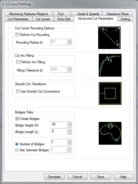 |
Bridges and/or Tabs
This option is ‘OFF’ by default, you may turn it ‘ON’ by selecting the Checkbox next to the text ‘Create Bridges’. By turning Bridges/Tabs ‘ON’, RhinoCAM will create ‘Bridges’ that maintain a connection between your part, and the full sheet of Material you are milling from. This will keep your part positioned on the table, and prevent any movement that may occur due to the smaller surface area : Vacuum Table Ratio. An example of a Bridge, is provided in Fig 9.2. Your ‘Bridges’ are defined by (3) Values:
1. Bridge Height: This is the height of each Bridge. (Recommended – 0.05in. or 1.5mm)
2. Bridge Length: This is the Length of each Bridge. (Recommended – 0.5in. or 12mm)
3. Quantity: This is the number of Bridges you would like to have. Controlled by ‘Number of Bridges’, which indicates an Absolute Quantity; or ‘Distance Between Bridges’, which creates a Bridge every ‘X’ inches or millimeters. (Use ‘Number of Bridges’, with a Value of ‘3’ for this Example)
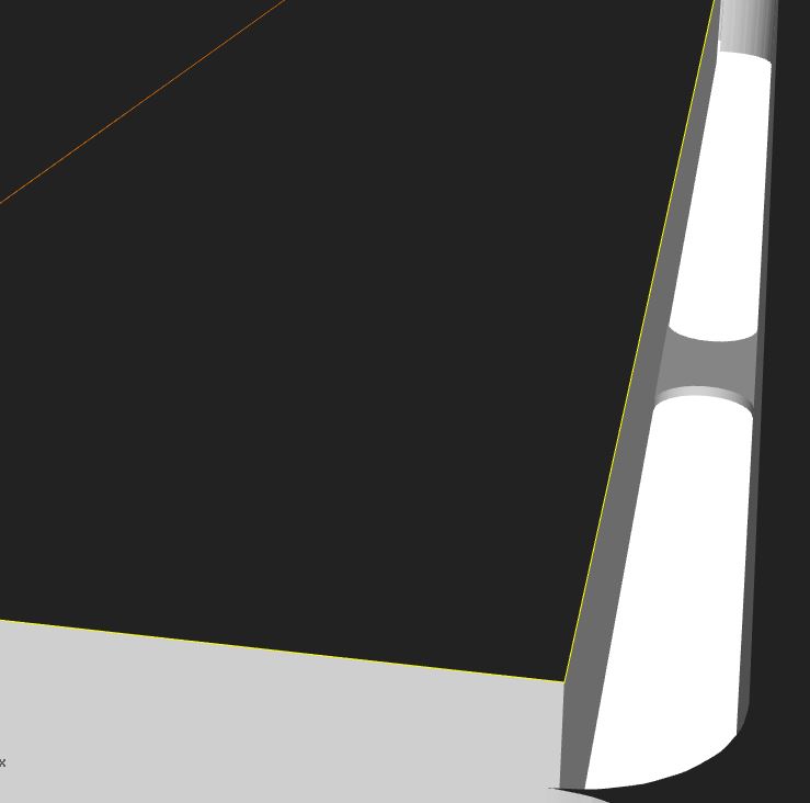
Fig 9.2 Bridges are defined by Height, Length, and Quantity. In the above example, the part was Profiled on the OUTSIDE of the highlighted Curve. A Bridge exists in the Profile Area, connecting the part to the Full Sheet. This eliminates movement, and if your settings are correct, the Bridges will be thin enough to break, sand, or cut off.
| Within the Entry/Exit Tab, we control how our Milling Tool ‘Engages’ or ‘Enters’ the material; and how the Milling Tool ‘Retracts’ or ‘Exits’ the Material. These settings are most useful in industry, primarily because they extend the Milling Tool-Life. While the settings aren’t entirely necessary for your needs, you can improve your cutting edges by programming a method of Entry.There are (3) Options for ‘Entry Motions; it is recommended that Users either change this setting to ‘None’; or ‘Along Path 3D Entry’. The ‘None’ Option simply eliminates any improved Entry Motion. The tool will Plunge directly downward into your material, and begin Milling. The ‘Along Path 3D Entry’ Option will program the tool to Engage the Material on a downward Angle Motion. The ‘Along Path Angle’, begins at the ‘Along Path Height’. Select one of these options, and you may leave any corresponding Values as Default.Exit Motions are less helpful, and can cause more of a headache than assistance. It is recommended that Users change the Exit Motion to ‘None’. |  |
| The Cut Level Values are the most important within the Profiling Operation. These settings control how the Milling Tool steps into your material. Say for instance, we were milling 3/4″ MDF; we can’t plunge the tool into the full 3/4″ of Material (unless we have a more advanced tool). Therefore, we program the tool to ‘step’ into the material, and repeatedly mill out the Profile Curve in multiple passes- rather than one, single pass. The tool will ‘step-down’ into the material; then mill out the Profile Curve; then it will ‘step-down’ again, and mill the same Profile Curve. It will repeat this process until it has reached a depth of our choosing. Follow these instructions thoroughly! Location of Cut Geometry The Cut Levels Tab, begins by asking the User Where the Cut Geometry is located; this is in reference to your Stock. For example, if we are milling from 3/4″ MDF, and we position our Profiling Curve Geometry at 3/4″ above the Rhino Grid/C-Plane; then our Geometry is located ‘At Top’. Alternately, if our Geometry was placed at ‘Z0’, or on the Rhino Grid/C-Plane; then our Geometry would be located ‘At Bottom’. It is highly recommended that all Users position their Geometry at the Top of their Stock. Reasoning and details behind the ‘At Top’ Selection, is discussed further as we continue through the Cut Levels Settings. |
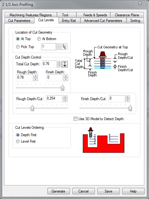 |
[Cut Depth Control] – Total Cut Depth
The ‘Total Cut Depth’ is asking for a Value that indicates how deep the Tool should go. This Value is measured from the Profile Geometry, and down. If you plan on cutting all the way through your material, then you should set this Value to whatever your material thickness may be.
Simplified: If you are cutting all the way through your material; your Value in this field is equal to your Material Thickness.
[Cut Depth Control] – Rough Depth & Finish Depth
In the settings below ‘Total Cut Depth’; we are asked to provide Values for ‘Rough Depth’ & ‘Finish Depth’. These fields are dividing your ‘Total Cut Depth’ into (2) two separate passes. Typically, your Rough Depth will occur first- it will program the tool to cut out your material very quickly, and your ‘Step-Down’ will be larger. This will equate to a faster cut time for your Roughing Passes. Your Finish Depth are passes that take away less material, to give your part a finer finish. This is useful when you are cutting out of Plywood, and will prevent ‘frayed edges’ on the bottom side of your material when the Milling Tool cuts through. Ultimately, applying any Finish Depth Settings will extend your Cutting Time, but can be useful on rare occasions. In short, Rough Depth + Finish Depth = Total Cut Depth. In hopes to minimize frustration, and maximize understanding; set your Finish Depth as ‘0’; and set your Rough Depth to match your Total Cut Depth.
Simplified: (Rough Depth) + (Finish Depth) = Total Cut Depth; It is recommended that you set your Rough Depth to match your Total Cut Depth, and your Finish Depth to ‘0’
[Cut Depth Control] – Rough Depth/Cut & Finish Depth/Cut
The next values are asking the User to divide their ‘Rough Depth’ & ‘Finish Depth’ into multiple passes. This is also more commonly known as ‘Step-Down’. Here, you are indicating the maximum Value the Tool is allowed to ‘Step-Down’ into your material. ‘Step-Down’ is determined by several factors, including Material Selection, Tool Selection, and Feed Rates. As a courtesy, dFAB has posted some of the more common ‘Step-Down’ Values with the Feeds and Speeds on our website. As an example, let us assume that we enter a value of 0.25″ in the Rough Depth/Cut Field. This would indicate that the Milling Tool will Step Down 0.25″ and cut out our Profile Geometry. Then, the Milling Tool will Step-Down another 0.25″ (0.25″+0.25″=0.50″) and repeat the cut on our Profile Geometry. The CNC Router will repeat this process until it reaches your ‘Rough Depth’. It will automatically calculate the remainder on the Final Pass, this means the CNC Router will:
1. Step-Down 0.25″, cut out Profile (Cut Depth is 0.25″)
2. Step-Down 0.25″, cut out Profile (Cut Depth is 0.50″)
3. Step-Down 0.25″, cut out Profile (Cut Depth is 0.75″)
4. Step-Down 0.01″, cut out Profile (Cut Depth is 0.76″)
To simplify and speed up your Toolpath, you should ‘get rid’ of this final pass of 0.01″; by changing the ‘Rough Depth/Cut’ Value to something like: (0.255″). This will eliminate the need for (4) Total Passes, and minimize the Toolpath to (3) Total Passes. *Note, because we set our ‘Finish Depth’ Value to (0) Zero, we do not have to program or input any values for ‘Finish Depth/Cut’
Simplified [Rough Depth/Cut]: (Rough Depth)/(Rough Depth/Cut) = (p), WHERE (p) = the number of Passes or ‘Steps’ the CNC Router will take to get to your (Rough Depth)
Simplified [Finish Depth/Cut]: (Finish Depth)/(Finish Depth/Cut) = (p), WHERE (p) = the number of Passes or ‘Steps’ the CNC Router will take to get to your (Finish Depth)
| In our final tab, Cut Parameters, we are bombarded with Values/Parameters. For the sake of ease, most of these settings are default, and need not a lengthy description. The important Parameter within this tab is located near the center with a Checkbox:Use Outside/Inside for Closed Curves:Select this Checkbox, and beneath the text, select the radio button that corresponds with which side you would like to cut for this operation. During this tutorial, we are cutting on the ‘OUTSIDE’ of a Closed Curve, so we must select the ‘Outside’ Option. After you’ve set this option, find and Select the button near the bottom of your window that says: ‘Generate’. | 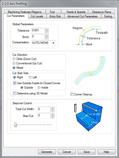 |
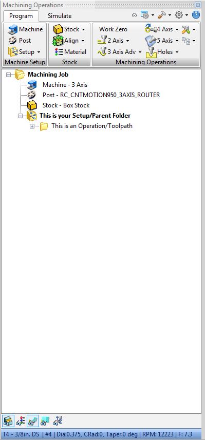
| You will have to set up a completely separate Profiling Operation if you would like to cut on the ‘INSIDE’ of a Closed Curve. This can be bothersome, as Users will have to re-input and re-create an entirely separate operation. There is a simple method for duplicating toolpaths; follow these instructions: 1. Find the ‘2 1/2 Axis Profiling’ Toolpath in your Machine Operations Browser. Right-Click the FOLDER ICON next to the Text Label. Select ‘COPY’ from the expanded menu. 2. Find the SETUP Folder within your Machine Operations Browser. This is the Parent Folder your 2 1/2 Axis Profiling Operation is located under. Right-Click the Parent Folder Icon, and Select ‘PASTE’ from the expanded Menu. 3. You should now have a Second Toolpath located under your Setup/Parent Folder. This Toolpath is a DUPLICATE of your copy/pasted operation. Open the Duplicate Toolpath settings by double-clicking the Folder Icon. You will have to change some settings to ensure the new operation functions properly: *Machining Features/Regions – You should ‘Remove All’ Drive Geometry, and select the Geometry you want to use for this newly created operation. In this case, we want to select all Geometry located on the ‘INSIDE – GEOMETRY’ Layer. *Advanced Cut Parameters – You should de-select the ‘Create Bridges’ Option. Bridges aren’t necessary for this scenario, but it is entirely up to the User whether or not they use Bridges and Tabs on future, non-tutorial related files. *Cut Parameters – You should change your ‘Use Outside/Inside for Closed Curves’; to the ‘INSIDE’ Option. Find and select the ‘Generate’ Button; you should now have a separate operation for the use of cutting on the ‘INSIDE’ of a Closed Curve. |
 |
Next Recommended Tutorial: Engraving Operations
END
Created by: P. Zach Ali
Date: 11.15.2013